0507347110/160114/B SHIELD fire safety solutions (5k1)
| INSTALLATION | EN - 22
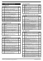
13.1 ShieldControl
13.2 Heat detector set(s)
13.3 Spark detector set
13.4 Smoke detector
13.5 Manual call point and fire alarm sounder
13.6 Sliding valves
13
COMMISSIONING CHECKLIST
#
Check
OK
1.
Is the ShieldControl panel connected to a clean
electrical group or a group not subject to regular
power failures by other equipment?
2.
Is the panel placed in an environment without
excessive dust in line with IP 30 or otherwise
placed in a cabinet?
3.
Are all cables checked for correct connection in
accordance with the electrical diagram?
4.
Are the EOL resistors removed from the
terminals that are in use and placed in the
connected equipment?
5.
Are the cables well guided and fixed?
6.
Is a shielded cable being used for all detectors
as well as the manual call point?
7.
Is the ShieldControl 5k1 switched to
RUN
mode?
8.
No fault signals on the ShieldControl panels?
#
Check
OK
1.
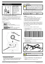
Are the heat detectors placed on top inside the
filter housing and in the hopper just above the
dustbin?
2.
Number of heat detector sets = number of
hoppers?
3.
Are the heat detectors wired in parallel and
connected to Zone 2 of ShieldControl?
4.
Is an EOL resistor of 5k1 placed in the last heat
detector?
5.
Is each heat detector being functionally tested
by gently heating it with a heat gun or heat lamp
and alarm signal being monitored by
ShieldControl?
#
Check
OK
1.
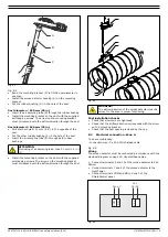
Are the spark detectors placed face to face in the
filter outlet duct?
2.
Ensure that the spark detector is not mounted
on the bottom of the duct.
3.
Are the spark detectors shielded against any
light and holes sealed with metal foil? Do not use
duct tape since this may let through infrared
light.
4.
Are the spark detectors wired in parallel and
connected to Zone 1 of ShieldControl?
5.
Is the last spark detector in the circuit provided
with REOL of 5k1 in line with ShieldControl 5k1?
6.
Is the earth connection properly made?
7.
Are the lenses clean?
8.
Are the spark detectors being functionally tested
through exposure to daylight and the signal
being monitored by ShieldControl?
#
Check
OK
1.
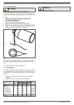
Is the smoke detector placed in the filter outlet
duct?
2.
Is the mounting bracket correctly installed in
relation to the airflow?
3.
Is the smoke detector connected to Zone 3 of
ShieldControl?
4.
Is the smoke detector being functionally tested
by test spray? Is the signal being monitored by
ShieldControl?
#
Check
OK
1.
Are the manual call points marked or placed
close to the ShieldControl panel in order to avoid
confusion with the general manual alarm boxes
of the building?
2.
Is the REOL that was placed in the manual call
point in line with the ShieldControl 5k1?
3.
Are the fire alarm sounders placed close to the
ShieldControl panel and fitted with the correct
EOL resistor 5k1?
4.
Is the sounder set to your local tone?
5.
Is sound level set to the maximum?
6.
Is the manual call point being functionally tested
and monitored by the ShieldControl?
7.
Is the fire alarm sounder being tested and
activated by ShieldControl?
#
Check
OK
1.
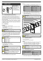
Can the ductwork carry the weight of the sliding
valves? If not, make sure the duct is properly
supported.
2.
Are the sliding valves mounted straight and
tension-free in the duct? Tension on the housing
results in inadequate sealing and noise by
airflow.
3.
Are the sliding valves pneumatically and
electrically wired?
4.
Are the reed contacts of the sliding valves
connected to the system control panel SCP?
5.
Are sliding valves mounted indoors? If not, are
they adequately protected against precipitation,
such as rain and snow?
6.
Is the compressed air pressure for the sliding
valves 4-5 bar and the compressed air dry and
oil-free?
7.
Do the sliding valves close in 4-5 seconds? If
not, reduce or increase pressure.
8.
Are the pneumatic and electrical wiring guided
away from potential fire places like duct and
filter?
9.
Make sure that the compressed air feed of the
sliding valves is an independent line and not via
the compressed air for the cleaning of the filter.
10.
Are the sliding valves functionally tested after a
fire test alarm in the complete system set up?
11.
Do the sliding valves close when filter system is
shut down and open at filter start up?
Содержание Shield 5k1
Страница 1: ...www plymovent com EN Fire safety solutions EN Installation and user manual shield 5k1...
Страница 30: ...SHIELD fire safety solutions 5k1 ELECTRICAL DIAGRAM 29 Electrical diagram 900010G0026 0 22 05 2014...
Страница 31: ......
Страница 32: ...www plymovent com 0507347110 160114 B SHIELD 5k1 EN...

