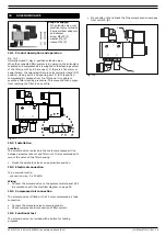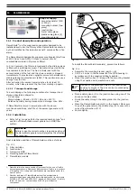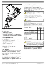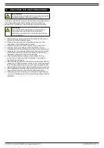
0507347110/160114/B SHIELD fire safety solutions (5k1)
| INSTALLATION | EN - 12
•
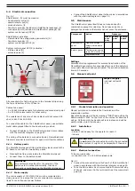
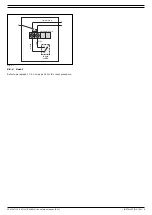
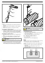
Mount the spark detector “EOL” in parallel after the one
without (“no EOL”) according to the electrical diagram on
page 29.
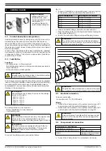
The spark detectors are provided with the following coloured
wires:
•
Connect the red and black wire to the 24V auxiliary
connection of the ShieldControl fire detection panel.
•
Connect the white and blue wire to Zone 1 of the
ShieldControl panel.
•
Connect the green wire to earth/ground.
The EOL resistor over Zone 1 of the ShieldControl panel has
become obsolete and has to be removed because it is already
premounted in the spark detector.
•
Remove the EOL resistor over Zone 1.
7.4
Functional test
The easiest way to test the spark detectors is to expose them to
daylight. Both detectors must be tested separately before the
system is put into operation.
To perform the test, proceed as follows.
•
Observe the functional testing instructions as
described in paragraph 4.4.
•
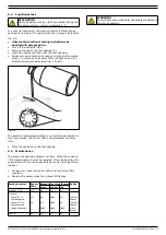
Loosen the fixation screw and remove one of the spark
detectors. That will expose the sensor to daylight.
•
Check the system status. ShieldControl should indicate a fire
in Zone 1.
•
Replace the spark detector and fasten it using the fixation
screw.
•
Press the
SYSTEM RESET
button on the ShieldControl panel.
•
Follow the same procedure for the other spark detector.
7.5
Maintenance
To be able to operate properly, the spark detectors must be kept
clean. Dirty lenses might influence their sensitivity. Both
detectors must be cleaned and tested periodically in accordance
with the national fire protection association regulations or the
authorities having local jurisdiction.
Cleaning intervals differ per situation and regular checks need
to be performed to set the cleaning interval for your specific
situation.
To clean and test the spark detectors, proceed as follows.
•
Make sure the FlameShield module(s) is/are disconnected.
•
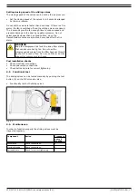
Loosen the fixation screw and remove one of the spark
detectors.
•
Clean the lens gently with a soft cloth or similar. In this way
it is exposed to daylight at the same time (ref. paragraph
7.4).
•
Check the system status. ShieldControl should indicate a fire
in Zone 1.
•
Replace the spark detector and fasten it using the fixation
screw.
•
Press the
SYSTEM RESET
button on the ShieldControl panel.
•
Follow the same procedure for the other spark detector.
If in both cases a fire is detected in Zone 1 of the ShieldControl
panel, the spark detectors are functioning properly. If no
detection takes place, the lens might still be polluted or the
spark detector is broken.
•
Clean and test once more.
•
If necessary: replace the broken spark detector.
•
Reconnect the FlameShield module(s).
Any detector that has been involved in a fire, abused or
damaged must be tested and replaced if necessary.
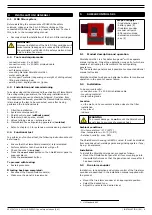
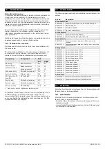
Colour codes wiring
Red +24
VDC
Black
0 VDC
White
24 V SIGNAL or ZONE +
Blue
ZONE –
Brown
TEST
Green
earth/ground
WARNING
To prevent a malfunction of the spark detector, ensure
that the green earth/ground wire is properly
connected.
WARNING
Failure to remove the EOL resistor over Zone 1 will
disable the monitoring function.
ATTENTION!
Notify all parties involved that you will be testing the
fire safety system; refer to paragraph 1.4.
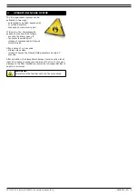
ATTENTION
The spark detectors must be tested one by one to
make sure they both react to daylight.
WARNING
The FlameShield module(s) must be disconnected to
avoid unintentional activation of the fire suppression
system.
Содержание Shield 5k1
Страница 1: ...www plymovent com EN Fire safety solutions EN Installation and user manual shield 5k1...
Страница 30: ...SHIELD fire safety solutions 5k1 ELECTRICAL DIAGRAM 29 Electrical diagram 900010G0026 0 22 05 2014...
Страница 31: ......
Страница 32: ...www plymovent com 0507347110 160114 B SHIELD 5k1 EN...


