0507347110/160114/B SHIELD fire safety solutions (5k1)
| INSTALLATION | EN - 10
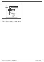
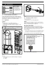
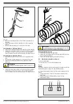
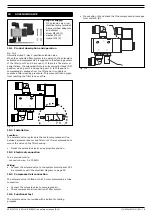
Fig. 6.4: Heat sensor no EOL resistor
The EOL resistor makes it possible for the fire detection panel to
monitor the wiring for open circuit.
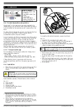
Alarm resistor
The heat detectors are fitted with a 470 ohm alarm resistor
(RAL) placed in series with the switching contact circuit. The
alarm resistors have no active function but do not interfere with
the functionality of the ShieldControl 5k1 fire detection panel
either. In case of a short circuit it will activate the fire alarm.
•
Connect the heat sensors in accordance with the electrical
diagram on page 29. Use shielded cables.
6.4
Functional test
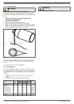
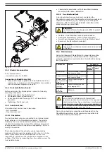
The operation of the heat detectors can be checked in two ways;
by measuring the ohm resistance:
- Gently heat the detectors using a heat gun or heat lamp.
by connecting them to the fire detection panel:
- Gently heat the detectors using a heat gun or heat lamp.
- Check the system status. ShieldControl should indicate a fire
in Zone 2.
To perform the test, proceed as follows.
•
Observe the functional testing instructions as
described in paragraph 4.4.
•
Functionally test all heat detectors.
•
Allow the detectors to cool down.
•
Reconnect the heat detectors.
6.5
Maintenance
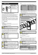
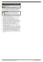
To be able to operate properly, the heat detectors must be kept
clean. They should be tested periodically in accordance with the
national fire protection association regulations or as directed by
the authorities having local jurisdiction.
•
Clean the detectors regularly and gently.
•
Test detectors for proper functioning; refer to paragraph 6.4.
•
Place detectors back in the filter housing.
Any detector that has been involved in a fire, abused or
damaged must be tested and replaced if necessary.
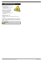
WARNING
Not using shielded cables can lead to a false alarm by
external high voltage sources and might activate the
alarm.
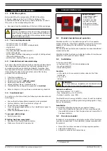
ATTENTION!
Notify all parties involved that you will be testing the
fire safety system; refer to paragraph 1.4.
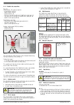
WARNING
Do not overheat the setpoint of the detector by more
than 55°C (131°F) because this can change the
default temperature setting.
Содержание Shield 5k1
Страница 1: ...www plymovent com EN Fire safety solutions EN Installation and user manual shield 5k1...
Страница 30: ...SHIELD fire safety solutions 5k1 ELECTRICAL DIAGRAM 29 Electrical diagram 900010G0026 0 22 05 2014...
Страница 31: ......
Страница 32: ...www plymovent com 0507347110 160114 B SHIELD 5k1 EN...


