137
PDP-433CMX
5
6
7
8
5
6
7
8
C
D
F
A
B
E
1
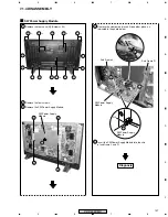
Remove the rear case (M).(Screws
×
20)
2
Remove the four screws.
3
Remove the SW Power Supply Module.
SW Power Supply Module
Diagnosis
4
Remove the clamper and insert it to another place, as
indicated in the photo below.
Clamper
Sub Frame L
Slit
SW Power Supply
Module
Sub Frame R
5
Insert the SW Power Supply Module into the slits
of sub frame L and R.
4
5
SW Power Supply
Module
SW Power Supply
Module
3
1
1
1
1
1
1
1
2
2
2
2
×
2
×
2
1
×
2
1
×
2
1
1
×
2
1
1
1
1
7.1.4 DISASSEMBLY
Содержание PDP 433CMX
Страница 14: ...14 PDP 433CMX Upper side 8 9 1 Upper side Upper side 9 7 5 6 2 10 10 8 8 2 5 UNDER LAYER SECTION 4 ...
Страница 26: ...26 PDP 433CMX 2 13 UPPER LAYER SECTION 2 10 10 12 SW101 100V 200V P4 P7 P3 P5 P6 P2 P1 VM1 6 7 4 8 5 1 9 3 ...
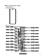
Страница 165: ...165 PDP 433CMX Pin Assignment Top View CXA3516R RGB ASSY IC4603 AD PLL IC ...
Страница 166: ...166 PDP 433CMX Block Diagram ...
Страница 167: ...167 PDP 433CMX Pin Function ...
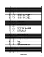
Страница 168: ...168 PDP 433CMX ...
Страница 169: ...169 PDP 433CMX ...

