Circuit description new circuits
GB 53
L9.2E
9.
FM/AM/
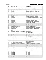
Ext_VC_AudioMono
FM, AM or external mono signal from
BiMOS to audio processor input (only
used in Mono and Nicam L sets)
Front/Ext1AudioL
Front audio Left input signal / External
1 Audio Left input signal.
Front/Ext1AudioR
Front audio Right input signal /
External 1 Audio Right input signal.
GND
Ground
GND_LOT
Ground of LOT
G_TXT_OSD
Green TXT or OSD signal from micro
processor to the video controller
IC7250 (BIMOS)
HD
Horizontal pulse derivation
HDRIVE
Horizontal output drive
HEW_protn
Switching signal to (de)activate the
XRAY protection which is measured
via pin 50 of the BIMOS (only for USA
sets)
Hflybk
Horizontal flyback pulse used to
monitor the horizontal oscillator
IF
Intermediate Frequency signal from
the tuner
12C (or IIC)
2 Wire communication protocol
between micro controller and
integrated circuits
IC
Integrated Circuit
I/O
Input/Output
INT
Audio internal output
IR
Output signal from infrared receiver to
micro controller.
KeyBd1
Local keyboard control signal to micro
controller
KeyBd2
Local keyboard control signal to micro
controller (In protection mode KeyBd2
is Ground)
KeyBd3
Local keyboard control signal to micro
controller
L-
Power amplifier output to headphone
and speaker
L+
Power amplifier output to speaker
LED
LED control signal from micro
controller to LED
LATAM
Latin America; schematic/PCB
information (only) applicable for Latin
American (incl. Brazilian) sets
LeftOut
Audio Left signal output
LTI
Luminance Transient Improvement (=
steepness)
MainAudioL/Mono
Audio Left/Mono signal to input power
amplifier
MainAudioR
Audio Right signal to input power
amplifier
MON
Audio monitor output
NICAM
Near Instantaneous Companded
Audio Muliplex (digital audio)
NR
Noise Reduction
NTSC
NTSC colour system
OSD On
Screen
Display
P0Sys1/AM
Switching signal with several
functions:
BiMOS crystal
selection (only for
Latam sets)
Selection of AM or FM signal (used in
combination with P1Sys2/
AMFM_ExtSel) (only for Europe)
P1Sys2/
AMFM_ExtSel
Switching signal with several
functions: BIMOS crystal selection
(only for Latam sets) Selection of
internal AM/FM signal or an external
signal (used in combination with
P0Sys1/AM)
P2LLp/Mtrap
Switching signal with several
functions: M-trap (sound filtering)
switching (only for A/P Pal Multi sets)
BiMOS crystal selection (only for
Latam sets), Selection of L or L'
system (only for Europe sets)
P3Dual/Mono
Switching signal to select the sound
filter in dual-system Mono sets (BG/I,
BG/DK or I/DK).
P4ScartPin8/SVHS
Switching signal from I/O to micro
controller with several functions:
Scart1 I/O: detects signal type
connected to Scart 1 (no signal, 16:9
signal, 4:3 signal) (only for Europe)
Cinch I/O: detects signal type
connected to cinch: SVHS or CVBS
(not for Europe)
P5BassSw
Bass switching signal (only for some
mono sets)
P6TrebleSw
Treble switching signal (only for some
mono sets)
P7Ext1/2
Used in L9-ITV sets (Hotel TV)
Pprotn
Signal from E-W and LOT output to
micro controller to (de)activate the
protection mode
P10Mute/Volume
Audio mute / Volume control signal pin
POR/CLK
Power on reset (only used in L9-ITV
sets)
R-
Power amplifier output " R- " to
speaker
R+
Power amplifier output " R+ " to
headphone and speaker
RAM
Random Access Memory
RESET
Reset signal to micro controller
RF_AGC
Automatic gain control signal from
BiMOS output to tuner input.
RGB
Red-Green-Blue
RGB_Blanking
Red Green Blue Blanking signal
(combined with AV_MUTE)
RightOut
Audio right signal output
R_TXT_OSD
Red TXT or OSD signal from uC to the
video controller IC7250 (BIMOS)
ROM
Read Only Memory
SAM
Service Alignment Mode. Service
mode for alignments and error buffer
display
SAP
Second audio program (only for USA
& A/P sets)
SCL
Clock line of the I2C-bus
SCL2
2nd Clock line of the IIC-bus (only
used in L9-ITV sets)
SDA
Data line of the I2C-bus
SDA2
2nd Data line of the I2C-bus (only
used in L9-ITV sets)
SDM
Service Default Mode. Service mode
with predefined settings for waveform
and voltage measurements, error
buffer display and option (byte)
setting.
SIF
Sound IF signal for FM audio
demodulator
SMPS
Switching Mode Power Supply
STANDBY
Switching signal from micro controller;
"low" for standby (power supply will be
switched to stand-by mode), "high" for
normal operation
SW_OUT
Selected Output signal from source
SYNC
Synchronisation
TBD
To Be Defined
TREBLE
Control signal for treble
TXT
Teletext
µ
C
Micro controller
Содержание L9.2EAA
Страница 5: ...Directions for use GB 5 L9 2E 3 3 Directions for use ...
Страница 6: ...Directions for use GB 6 L9 2E 3 ...
Страница 7: ...Directions for use GB 7 L9 2E 3 ...
Страница 31: ...Schematics and PWB s GB 31 L9 2E 7 ...
Страница 32: ...Schematics and PWB s GB 32 L9 2E 7 ...
Страница 38: ...Schematics and PWB s GB 38 L9 2E 7 ...
Страница 42: ...Schematics and PWB s GB 42 L9 2E 7 Personal notes Personal notes ...

