Circuit description new circuits
GB 52
L9.2E
9.
the BIMOS is used as the feed back input from the CRT base
panel.
9.6.9
Beam current limiting
A beam current limiting circuit inside the BiMOS handles the
contrast and brightness control for the RGB signals. This
prevents the CRT tube being over driven, which may cause
serious damage in the line output stage. The reference used for
this purpose is the DC voltage on Pin 22 (BLCIN) of the TV-
processor. Contrast and brightness reduction of the RGB
output signals is therefore proportional to the voltage present
on this pin. Contrast reduction starts when the voltage on pin
22 is lower than 3.0 V. Brightness reduction starts when the
voltage on pin 22 is less than 2.0 V.
The voltage on pin 22 is normally 3.3V (limitor not active). To
enable correct operation however, an external adaptation to
the circuit is required for the correct functioning of the limiting
function. This is connected to Pin 22, the circuit therefore
ensures that correct peak white limiting and the average beam
current limiting takes place. Components 6212, 3246 are for
the average beam current limiting. As a reference for the
average beam current control the signal ABL_info is used. This
signal is a measurement of the picture contents. As the time
constant of the filter is much bigger than the frame period time,
the DC at the anode of 6212 represents the average value of
the picture content. Via 6212 and 2226 the DC voltage at pin
22 is slowly. The RGB output signals are applied to the CRT
panel via connector 0243. Via diodes 6213, 6214 and 6215 and
series resistor 3214, the RGB signals are also connected to the
CRT_discharge signal. The level of this signal is only high
during the time the set is switched off. And id due to the
cathodes of the CRT are driven fully negative. That means that
the beam current is increased. and consequently the CRT
quickly discharged.
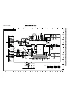
9.6.10 CRT panel (see circuit diagram B)
On the CRT panel the analog output amplifiers for the RGB
signals are located.
The B-signal is amplified by the analog amplifier formed by a
circuit build around the transitors 7331, 7332 and 7333.
The G- signal is amplified by the analog amplifier formed by a
circuit build around the transitors 7321, 7322 and 7323. The
R- signal is amplified by the analog amplifier formed by a circuit
build around the transitors 7311, 7312 and 7313.
The supply voltage for the transistors is +160VA and is derived
from the line output stage.
9.7
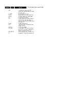
List of abbreviations
2CS
2 Carrier Stereo
A/P
Asia Pacific; schematic/PCB
information (only) applicable for Asia
Pacific sets
AFC
Automatic Frequency Control
AQUADAG
Aquadag coating on the (outside of
the) picture tube
AudioOutR
Audio signal at Right output channel.
AudioOutL/Mono
Audio signal at Left output channel /
Mono output channel.
AV_MUTE
Signal to mute the sound on the Audio-
out of Cinch / Scart (Combined with
RBG_Blanking)
Ext2Fun_SW
(AV_Mute/
Ext2Fun_SW)
Switching signal from Scart2 to micro
controller indicating the presence and
type of signal on Scart2. (no signal /
CVBS 16:9 / CVBS 4:3)
AV
Audio Video signal
AVL
Automatic Volume Level
B_TXT_OSD
Blue TXT or OSD signal from uC to the
video controller IC7250 (BIMOS)
BASS
Control signal for BASS
BCI
Beam Current information
BTSC
Broadcast Television Standard
Committee; sound standard for
America and Asia Pacific
Buzzer
Buzzer (only used in L9-ITV)
CRT DISCHARGE
Fast drop of VBATT during after switch
off the set. Which result in EHT voltage
reducing to less than 18 kv within 5
sec.
CTI
Colour Transient Improvement
CVBS
Colour Video Blanking
Synchronisation. Video signal
containing colour, black/white,
blanking and synchronisation
information.
CVBS_EXT
CVBS external = CVBS signal form
external source (VCR, DVD etc.)
CVBS_INT
CVBS internal = CVBS signal from the
tuner
CVBS_MON
CVBS monitor (CVBS) signal to Cinch
or Scart
CVBS_Terr
CVBS Terrestrial output signal
CVBS_TXT
CVBS for TXT processing in micro
controller
Din
Digital input signal only used in L9-
ITV)
Dout
Digital output signal (only used in L9-
ITV)
DBX
Dynamic Bass Expander (only used
for BTSC sound system)
DNR
Dynamic Noise Reduction
EAR
Earth (ground layer)
EEPROM
Electrically Erasable Programmable
Read Only Memory (also called NVM;
non-volatile memory)
EHT-INFO
Extra high tension information; Beam
current related signal from CRT to
BIMOS.
Ext1 B
RGB External 1 Blue input signal.
Ext1 FB
RGB External 1 Fast-blanking input
signal.
Ext1 G
RGB External 1 Green input signal.
Ext1 R
RGB External 1 Red input signal.
Ext1 Video
RGB External 1 Video input signal.
Ext2 AudioL/Mono
External 2 Audio Left input signal /
Mono input signal.
Ext Audio/Mono
External Audio input signal / Mono
input signal.
Ext2 AudioR
External 2 Audio Right input signal.
Ext2C
Exterial 2 SVHS Chrominance (C)
input signal.
Ext2Video/Y
External 2 Video input signal or SVHS
Luminance (Y) input signal.
ESD
Electrostatic Discharge
EURO
Europe; schematic/PCB information
(only) applicable for European sets
EWD_dyn
Dynamic East-West correction to
compensate for variations in EHT
EWDRIVE
East-West drive correction
FB_TXT_OSD
Fast blanking signal from micro
controller to IC7250 (BIMOS) for
inserting or displaying TXT and OSD
information (generated by the micro
processor)
Filament
Filament (heater voltage) from LOT to
CRT
FBL
Fast Blanking
FFBL
Full screen Fast Blanking
Содержание L9.2EAA
Страница 5: ...Directions for use GB 5 L9 2E 3 3 Directions for use ...
Страница 6: ...Directions for use GB 6 L9 2E 3 ...
Страница 7: ...Directions for use GB 7 L9 2E 3 ...
Страница 31: ...Schematics and PWB s GB 31 L9 2E 7 ...
Страница 32: ...Schematics and PWB s GB 32 L9 2E 7 ...
Страница 38: ...Schematics and PWB s GB 38 L9 2E 7 ...
Страница 42: ...Schematics and PWB s GB 42 L9 2E 7 Personal notes Personal notes ...

