Service Modes, fault finding and repair tips
GB 11
L9.2E
5.
5.3
The menus and submenus
5.3.1
Tuner sub menu
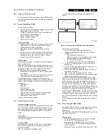
The tuner sub menu contains the following items:
•
IF_PLL
: PLL Alignment for all PAL/SECAM
systems, excluding SECAM-LL'
•
IF_PLL POS
: PLL Alignment for SECAM-LL'
•
IF_PLL OFFSET
: Default value = 48 ; Do not align
•
AFW
: AFC Window
•
AGC
: AGC take-over point
•
YD
: Default value = 12 ; Do not align
•
CL
: Default value = 4 ; Do not align
•
AFA
•
AFB
The items AFA and AFB can not be selected, they are for
monitoring purposes only.
The commands MENU UP and MENU DOWN are used to
select the next/previous item.
The commands MENU LEFT and MENU RIGHT are used to
increase/decrease the value of the selected item. The changed
values will be send directly to the related hardware.
The item values are stored in NVM if this sub menu is left.
5.3.2
White tone sub menu
The commands MENU UP and MENU DOWN are used to
select the next/previous item.
The commands MENU LEFT and MENU RIGHT are used to
increase/decrease the value of the selected item. The changed
values will be send directly to the related hardware.
The item values are stored in NVM if this sub menu is left.
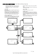
The white tone sub menu contains the following items:
•
NORMAL RED
•
NORMAL GREEN
•
NORMAL BLUE
•
DELTA COOL RED
•
DELTA COOL GREEN
•
DELTA COOL BLUE
•
DELTA WARM RED
•
DELTA WARM GREEN
•
DELTA WARM BLUE
OSD is kept to a minimum in this menu, in order to make white
tone alignment possible.
The Contrast Plus feature (black stretch) is set to OFF when
the white tone submenu is entered.
5.3.3
Audio sub menu
The tuner sub menu contains the following items:
•
A-FM
: Default value = 232 ; Do not align
•
AT
: Default value = 4 ; Do not align
•
STEREO
: Default value = 15 ; Do not align
•
DUAL
: Default value = 12 ; Do not align
The sound adjustments sub menu are not available in Mono
sets.
The presence of an item in the menu strongly depends on the
selected soundboard (option SB).
5.3.4
Geometry sub menu
The geometry sub menu contains the following items:
•
VAM : Vertical amplitude
•
VSL : Vertical slope
•
SBL : Service blanking
•
HSH : Horizontal shift
•
H60 : Default value = 10 ; Do not align
•
V60 : Default value = 12 ; Do not align
•
VSC : Vertical S correction
•
VSH : Vertical shift
5.4
Error code buffer and error codes
5.4.1
Error code buffer
The error code buffer contains all errors detected since the last
time the buffer was erased. The buffer is written from left to
right.
•
when an error occurs that is not yet in the error code buffer,
the error is written at the left side and all other errors shift
one position to the right
•
the error code buffer will be cleared in the following cases:
1.
exiting SDM or SAM with the "Standby" command on
the remote control
2.
transmitting the commands "EXIT" with the DST
(RC7150)
3.
transmitting the commands "DIAGNOSE-9-9-OK" with
the DST.
•
The error buffer is not reset by leaving SDM or SAM with
the mains error buffer is not switch.
Examples:
•
ERROR: 0 0 0 0 0 : No errors detected
•
ERROR: 6 0 0 0 0 : Error code 6 is the last and only
detected error
•
ERROR: 5 6 0 0 0 : Error code 6 was first detected and
error code 5 is the last detected (newest) error
5.4.2
Error codes
In case of non-intermittent faults, clear the error buffer before
starting the repair to prevent that "old" error codes are present.
If possible check the entire content of the error buffers. In some
situations an error code is only the RESULT of another error
code (and not the actual cause).
Note: a fault in the protection detection circuitry can also lead
to a protection.
a.
Error 0 = No error
b.
Error 1 = X-ray ( Only for USA sets )
c.
Error 2 = High beam current protection
High beam protection active; set is switched to protection;
error code 2 is placed in the error buffer; the LED will blink
2 times ( repeatedly ).
As the name implies, the cause of this protection is a too
high beam current (bright screen with flyback lines). Check
whether the +160V supply to the CRT panel is present. If
the voltage is present, the most likely cause is the CRT
panel or the picture tube. Disconnect the CRT panel to
determine the cause. If the +160V voltage is not present,
check R3416 and D6409 ( Horizontal Deflection - A2 )
EW protection:
If this protection is active, the cause could be one of the
following items;
horizontal deflection coil 5445
S-correction capacitor 2407
flyback capacitor 2434
line output stage
short circuit of flyback diode 6434
EW power-transistor 7402 or driver-transistor 7400
d.
Error 3 = Vertical / Frame protection
There are no pulses detected at pin 37 of the main
microprocessor 7600 ( panel A7 ).
If this protection is active, the causes could be one of the
following items;
IC 7460 is faulty ( A3 )
Open circuit of vertical deflection coil
V13V not present and/or Vlotaux -13V not present
Resistor 3463
Transitor 7609 is defect ( A7 )
e.
Error 4 = Sound processor ( IC7803 ) I2C error (
MSP3415D )
Sound processor does not respond to the micro controller
f.
Error 5 = Bimos ( IC7250 ) start-up error ( POR bit )
Содержание L9.2EAA
Страница 5: ...Directions for use GB 5 L9 2E 3 3 Directions for use ...
Страница 6: ...Directions for use GB 6 L9 2E 3 ...
Страница 7: ...Directions for use GB 7 L9 2E 3 ...
Страница 31: ...Schematics and PWB s GB 31 L9 2E 7 ...
Страница 32: ...Schematics and PWB s GB 32 L9 2E 7 ...
Страница 38: ...Schematics and PWB s GB 38 L9 2E 7 ...
Страница 42: ...Schematics and PWB s GB 42 L9 2E 7 Personal notes Personal notes ...


