background image

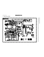
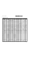
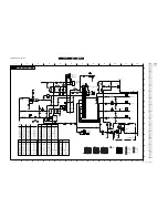
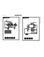
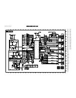
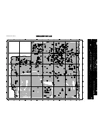
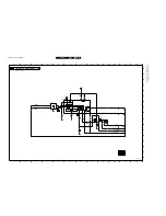
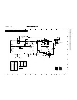
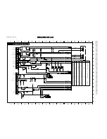
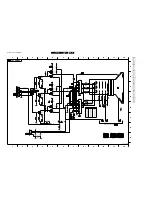
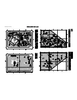
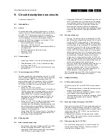
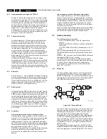
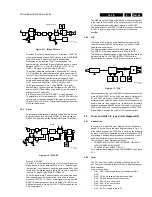
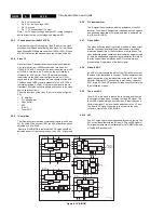
Schematics and PWB’s

GB 36

L9.2E

7.

A13-76

A5-41

Audio L I/P

A13-57

1

A13-41

6

G

H

0105 E3
0214 A11
0216 B11
0223-A A2
0223-B E2
0227 E6
0229 H6
1101 A4
1102 B3
1103 B4
1104 C5
1105 C3
1106 C3
1107 C4
1108 D4
1109 D3
1110 A3
1111 E2
1113 F3
1115 G2

2

A13-44

A13-50

8

0V7

0V7

To 0253 of

Audio L O/P

or 0249 of

2

0V7

Audio R I/P

or 0230 of

A5-38

A6-54

Video 2/Y I/P

1

2

3

4

5

6

7

8

9

10

11

12

1

2

3

4

0V7

A13-50

1V8

5V

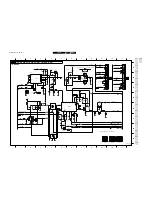
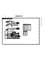
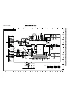
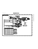
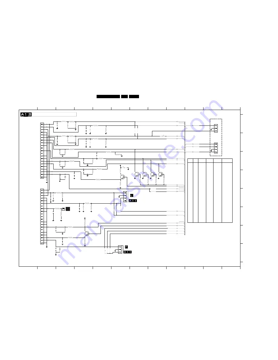
REAR I/O SCART  (EUROPE)

6

9

F

A6-57

7

5

6

7

8

9

10

11

12

A

B

C

D

E

F

A13-55

7

11

SCART  2

A13-44

A6-60

A12-13

D

H

1117 H2
1118 G3
1119 F2
1132 D3
2101 A3
2102 A4
2103 B3
2104 B4
2105 C6
2106 B8
2107 E2
2109 F3
3100 A3
3101 A4
3102 A5
3103 A5
3104 B3
3105 B4
3106 B5
3107 B5
3108 B3
3109 C3
3110 C4

BC847B

-

4K7

-

-

4141

-

Yes

Yes

Yes

Yes

RF/Video2 Switching

BC847B

A5-42

-

A6-50

12

-

BZX284

-

BZX284

-

3111 C5
3112 C3
3113 C3
3114 D4
3115 C5
3116 D5
3118 E3
3119 E3
3120 E4

11

A6-58

E

A6-55

2V4

1V8

A13-76

C

To 0252 of

5V

3

A5-43

3121 F4
3122 B5
3123 C6
3124 G3
3125 G3
3128 G3
3130 D7
3131 D7
3132 D8
3133 D8
3135 F3
3136 F3
3140 D6
3141 D6
3142 F4
3143 G4
4131 A7
4132 A7

4

5

Audio R O/P

10

2V4

7141

-

-

A7-12

for ITV only

4133 F6
4139 H5
4140 F6
4141 H5
4142 H5
4143 E8
4147 F6
4148 E8
5100 A3
5101 B3
6107 D3
6110 H3
7130 D7
7131 D7
7132 D8
7133 D8
7140 D6
7141 G4

Audio L I/P

A6-61

SCART  1

1

A13-57

9

A5-44

-

-

Yes

C6V8

Jumper

Jumper

Jumper

3142

-

Jumper

-

-

Yes

-

4139

RGB G I/P

RF/Video1 Switching

RGB R I/P

-

4133

-

-

-

3120

-

2105

100u

Cinch Mono

SC1,SC2

Stereo

SC1,Front

47K

-

3106

-

330pF

-

330pF

BC847B

7140

4133

3121

47K

1106

4139

100R

3111

+5VA

0105

1

3140

680R

3106

1K

4K7

3135

1105

100R

3125

1108

15K

3136

TO 0605

3130

33R

1115

4132

2

3

0229

1

7132

4143

 C I/P

CVBS O/P

A6-59

4

C6V8

A13-50

12

8

CVBS O/P

RGB FB I/P

A13-76

10

B

5

G

A

3

RGB B I/P

Audio R O/P

Video 1 I/P

Audio R I/P

Audio L O/P

-

-

Yes

A13-55

2A

20A

21A

3A

4A

5A

6A

7A

8A

9A

4131

0223-B

Yes

-

-

-

-

75R

-

75R

-

3125

-

4147

Yes

-

-

-

Yes

6110

-

75R

-

3135

1K

1K

Jumper

4K7

-

3136

-

9649

Yes

-

-

3140

Jumper

Jumper

Jumper

3107

47K

47K

47K

47K

-

Jumper

-

3143

-

1K

-

1K

-

47K

-

-

A

A,B

A

1K

-

Jumper

-

-

-

4140

-

-

-

3124

Yes

Yes

Yes

2107

-

330pF

-

100R

-

100R

-

3128

-

75R

-

3102

1K

1K

SC1

Mono

SC1,Front

3103

-

-

47K

15K

-

15K

1K

1K

1K

1K

Cinch Stereo

SC1,SC2,Side

AV Stereo

0223

Yes

Yes

Yes

3118

-

1K

-

Jumper

-

3119

Yes

0229

-

-

330pF

-

2109

A,B

A

0227

-

3121

-

47K

220K

1110

330p

2101

3105

75R

3112

4142

10u

2106

75R

3128

3110

75R

1111

+5VA

3124

75R

3123

6K8

3116

75R

2103

330p

2107

3104

150R

330p

75R

3109

1

2

3

4

150R

3100

1119

0216

4148

1103

330p

2104

100R

3115

1132

3119

47K

3114

75R

33R

3133

330p

2102

4141

1K

3102

1118

3B

4B

5B

6B

7B

8B

9B

330p

2109

1B

10B

11B

12B

13B

14B

15B

16B

17B

18B

19B

2B

20B

21B

33R

3131

100R

3113

4147

3118

1104

1K

3120

1K

0223-A

1A

10A

11A

12A

13A

14A

15A

16A

17A

18A

19A

47K

3103

7131

6110

BZX284-C6V8

220K

3101

3142

680R

1U

5100

1U

5101

1113

1109

3122

10K

7130

100R

3108

0214

1

2

3

47K

3107

BC847B

7141

1102

0227

1

2

3

4

1101

3132

33R

3141

1K

BZX284-C6V8

6107

4140

1107

7133

1117

3143

1K

ScartPin8|SVHS

Ext1FB

Ext2Video

Ext1Video

Ext2AudioL|Mono

AV_Mute

Ext1B

Ext1R

Ext1G

Ext2C

VideoOut

Ext2Video|Y

AudioOutR

VideoOut

VideoOut

Ext1Video

ExtAudioMono

Ext2AudioL|Mono

Ext1AudioR

Ext1AudioL|Mono

Ext2C

AudioOutL|Mono

Ext2Video|Y

Ext2Video

CL 96532028_048.eps

070499

A7

Содержание L9.2EAA

Страница 1: ...age diagram 19 Blockdiagram 20 Testpointsoverview and oscillograms 21 7 Electrical diagram s en PWB s Diagram PWB Power supply Diagram A1 22 31 32 Diversaty table A1 23 Horizontal deflection Diagram A2 24 31 32 Vertical deflection Diagram A3 25 31 32 Synchronisation Diagram A4 25 31 32 Tuner en video IF TDA 8844 Diagram A5 26 31 32 Tuner en video IF TDA 8845 Diagram A5 27 31 32 Diversaty table A5 ...

Страница 2: ...2 2VRMS 10kΩ j 7 Blue 0 7Vpp 75 j 8 CVBS status INT 0 2V EXT 16 9 4 5 7V EXT 4 3 9 5 12V 9 Earth screen v 10 11 Green 0 7Vpp 75 j 12 13 Earth screen v 14 Earth screen v 15 Red 0 7Vpp 75 j 16 FBL 0 9V RGB mode 17 Earth screen v 18 Earth screen v 19 CVBS k 20 CVBS 1Vpp 75 j 21 Earth screen v 1 2 2 EXT2 CVBS in out SVHS in Input EXT2 output tuner Input tuner EXT1 output tuner EXT11 1 Audio Out R 0 5V...

Страница 3: ...to the deflection coil Other components through which the deflection current flows Note This resoldering is advised to prevent bad connections due to metal fatigue in solder joints and is therefore only necessary for television sets older than 2 years The wire trees and EHT cable should be routed correctly and fixed with the mounted cable clamps The insulation of the mains lead should be checked f...

Страница 4: ...picture tube the method shown in Fig 2 1 should be used to discharge the picture tube Use a high voltage probe and a multimeter position DC V Discharge until the meter reading is 0V after approx 30s 5 Together with the deflection unit and any multipole unit the flat square picture tubes used form an integrated unit The deflection and the multipole units are set optimally at the factory Adjustment ...

Страница 5: ...Directions for use GB 5 L9 2E 3 3 Directions for use ...

Страница 6: ...Directions for use GB 6 L9 2E 3 ...

Страница 7: ...Directions for use GB 7 L9 2E 3 ...

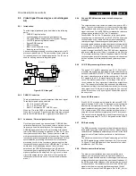
Страница 8: ...c Test points for the Tuner Video IF circuit A5 L1 L2 L3 etc Test points for the Line deflection circuit A2 P1 P2 P3 etc Test points for the power supply A1 S1 S2 S3 etc Test points for the synchronisation circuit A4 V1 V2 V3 etc Test points for the video processing circuit CRT panel A6 CRT panel B Measurements are performed under the following conditions Video colour bar signal audio 3kHz left 1k...

Страница 9: ...shows all OSD incl error buffer Access to SAM By pressing the CHANNEL DOWN and VOLUME DOWN buttons on the local keyboard simultaneously or pressing ALIGN on theDST DST the set switches from SDM to SAM In the SDM the following information is displayed on the screen Figure 5 3 Service Default Mode screens and structure Explanation notes references 1 1 LLLL Operation hours timer hexadecimal 2 2 Softw...

Страница 10: ...e SAM remains displayed in top of screen Pressing the MENU key again will return to the last SAM status Pressing the OSD button of the remote control shows only SAM in the top of screen Access to SDM Pressing the DEFAULT button on the DST SAM menu control Menu items AKB VSD Tuner White tone Geometry and Audio can be selected with the MENU Up or MENU DOWN key Entry into the selected items sub menus...

Страница 11: ... from left to right when an error occurs that is not yet in the error code buffer the error is written at the left side and all other errors shift one position to the right the error code buffer will be cleared in the following cases 1 exiting SDM or SAM with the Standby command on the remote control 2 transmitting the commands EXIT with the DST RC7150 3 transmitting the commands DIAGNOSE 9 9 OK w...

Страница 12: ...he BIMOS 7250 D pin 40 A4 Synchronisation Timer IC 7607 or transitor 7608 is defect A7 Control 2 Note If the Collector of 7402 is shorted to the Emitter hick up noise can be heard from the power supplyIn this case the E W protection is disabled is correctly working a parabolic picture 3 Also take note of protection circuits in the line output stage If any of these circuits are activated the set wi...

Страница 13: ... 1 Communication to the television automatic 2 Asking questions to you manually ComPair combines this information with the repair information in its database to find out how to repair the L9 2E Automatic information gathering Reading out the error buffer ComPair can automatically read out the contents of the entire error buffer Diagnosis on I2C level ComPair can access the I2C bus of the televisio...

Страница 14: ...red LED on the Compair interface wil light up 12 Switch on the television set with the mains switch 13 When the set is in standby Click on Start up in ComPair mode from standby in the ComPair L9 2E fault finding tree otherwise continue Figure 5 7 Figure 5 8 The set has now started up in ComPair mode Follow the instruction in the L9 2E fault finding tree to diagnose the set Note that the OSD works ...

Страница 15: ... of the power supply is too high Isolate each branch of the load one by one until the hicking disappear Continue with the fault finding for the branch which causes the overload The branches are A1 AudioSupply VBATT MainSupply Vaux Yes Check A7 C1 C4 reset 3V3 Check Replace TS7602 TS7605 IC7600 X1600 A8 LED6690 Yes A No A1 voltage on TR5545 pin9 present No Check Replace A1 L5540 D6540 C2540 Yes Not...

Страница 16: ... unstable C NO Picture NO Sound Menu OK Check Replace A5 Antenna D6007 A6 X1205 X1208 Sound and Picture from external source OK Check Replace Tuner1000 Check Replace IC7250 No Yes 1 1 3 0 1 1 3 0 1 1 3 0 1 1 3 0 1 1 3 0 1 1 3 0 Picture OK Menu OK NO Sound l r l r A5 I9 Ok Ok Ok Check Replace A5 TS7268 TS7000 FIL1001 FIL1002 Yes Yes Yes No Check Replace A5 IC7250 Check Replace A10 TS7951 No No A5 L...

Страница 17: ...l section Vertical picture is too small or unstable A4 S2 OK Check Replace A4 IC7250 No Yes Check Replace A2 TS7400 TS7402 LOT 5445 C2407 A7 IC7607 TS7608 A4 S3 S4 OK Check Replace A4 IC7250 No A3 F3 F4 F5 OK Check Replace IC7460 R3463 R3465 R3466 D6460 C2464 No Yes Check Replace A3 Vertical defl coil L0222 Yes 1 5 3 0 1 3 3 A 1 5 3 0 1 1 7 8 1 1 7 8 CL 96532028_011 eps 290399 ...

Страница 18: ... A2 VLotAux 5V Yes ERROR 4 Fault in audio section In this situation the set turns on without sound Message ERR 4 0 0 0 0 Check Replace A10 VlotAux 5V 7803 pin9 10 1 7 X ERROR 11 I2C Tuner error It is possible that during 5V protection Error 4 will be reported too Message ERR 11 0 0 0 0 CheckReplace A5 Tuner1000 1 1 2 0 EEPROM error When I2C signals or the 5D are missing on IC7601 the set can funct...

Страница 19: ...50 49 SDA SCL 3625 7601 ST24W0431 EEPROM 7600 SAA5565 µC CONTROL IIC BUS INTERCONNECTION DIAGRAM SUPPLY VOLTAGE DIAGRAM A7 FOCUS VG2 EHT FOCUS VG2 3 2 9 filement 3416 0220 3316 3336 3326 3349 6409 VLOT AUX 13V VLOT AUX 5V 5VA 5 6402 3 2 0244 ANODE CRT FOCUS VG2 3350 VLOT 8V 3 3411 6412 CL 96532028_002 eps 140499 13V VLOT AUX 13V 5571 PRESENT FOR 2W 3W AUDIO AUDIO SUPPLY 10V 14VA AUDIO SUPPLY 10V 1...

Страница 20: ...4 QSS MIXER SOUND AM DEM FM AUDIO DET SOUND AM DEM 2 MONO SIF IF 7250 A TDA 8844 EXT AUDIO AUDIO OUT FM AUDIO MONO A9 SIF DUAL MONO AUDIO QSS MIXER ONLY FOR NICAM L SETS 2 15 56 55 I4 I3 A10 A13 A7 A13 D1 A5 AGC 7250 A TDA 8845 4 5 MHz 5 5 MHz 6 0 MHz 6 5 MHz 7254 7703 7704 3710 A7 A7 A13 5551 A7 6212 A2 2537 3 7 8 2 3525 37 A2 HEW_PROTN 5444 3400 7400 BF422 7 2 1 5445 VLOT AUX 13V V_GUARD A7 2417...

Страница 21: ...53 7954 A28 A27 A26 A25 A26 A28 A27 A25 V1 3212 1572 9234 L4 uC 17 1 17 1 P3 13V DC 0 5V div DC 5ms div 0 5V div DC 5ms div 10V div DC 5ms div 2V div DC 5ms div 0 5V div DC 5ms div 0V 0 2V div DC 5µs div 1V div DC 5µs div 1V div DC 2µs div 0 5V div AC 20µs div 0 5V div AC 20µs div 1V div DC 0 5µs div 50V div DC 10µs div 50V div DC 20µs div 50V div DC 10µs div 1V div DC 5µs div 1V div DC 5µs div 0 ...

Страница 22: ... 4510 D10 5500 C4 5501 B4 5502 E6 5516 C7 for ITV only 1N5062 Only V Normal Operation V StandBy Operation Europe Only 1V2 Only 2V4 3V2 1V1 0V7 95V 9V5 G STP6NA60 2V5 2V6 ADJ 9V5 2V5 6500 B4 6501 B3 6502 B6 6503 B5 6504 B5 6505 B6 6507 B6 6508 C6 6510 D4 6520 D6 6521 D6 2 AUDIO O P 2W 3W 1W 5570 5572 9504 B3 9506 C5 MainSupply95V 90 276 V FULL RANGE VBATT only 2V 0211 1 P1 4K7 3540 47R 3541 DSP 100...

Страница 23: ...3n3 220u 25 220u 25 27K 27K 27K 27K 1n 1n 1n 680p 1n 1n 680p 5521 3u3 2u2 4n7 4n7 4n7 3n3 5n6 4n7 3n3 27K 27K 2u2 2u2 2u2 680p 680p 2550 150E DASUNG DASUNG 2510 ELDOR DASUNG DASUNG 150E 150E 150E 150E 150E 150E 150E 150E 27K 4n7 3n3 3n3 3n3 47K 27K 3536 27K 39K H SINK H SINK 680p 330p IN5602 IN5602 IN5602 BLACK BLACK BLACK BLACK H SINK H SINK H SINK H SINK 680p 3n3 2522 4n7 BLACK BLACK H SINK H SI...

Страница 24: ... E9 6418 E6 6419 E6 6431 C4 6432 C3 6433 B5 6434 C6 6435 C3 7400 E4 7401 B10 7402 D5 7403 F10 7404 F11 7431 C2 9402 B5 9403 C10 9404 E10 9408 C6 9424 B5 56u 2V4 10V 9V5 31V 6401 E3 6402 C9 6403 F9 6404 D6 6405 E9 47K FOR ITV fish hook A6 62 A4 62 3441 F10 3440 F9 3436 E5 3407 B5 3411 D10 3412 F9 3414 B8 3415 B8 3416 A8 3417 D10 3418 F10 3419 F10 3420 E4 3421 E3 3423 B9 3424 B10 3425 C10 3426 F10 3...

Страница 25: ...os VlotAux13V CRT_Discharge VdriveNeg V_Guard 100n 2465 CL 96532028_037 eps 070499 0 5V div DC 5ms div 0 5V div DC 5ms div 10V div DC 5ms div 2V div DC 5ms div 0 5V div DC 5ms div F1 F2 F3 F5 F4 5V A3 64 AVL 3274 E4 3275 E5 3276 E4 5205 B4 5405 B5 7250 D C3 0V7 1V4 2V4 3V8 SYNCHRONISATION A2 62 0V2 A7 7 2 3 4 5 6 A B C D E F G H A B C D E F G 2V3 A2 32 A2 81 3V 2234 C3 2235 D5 2236 C5 2237 D2 2238...

Страница 26: ...006 47p 3204 100R 470R 3212 3034 1K 3016 680R 3K3 3227 12K 3003 10 11 4 SCL 5 SDA 1000 7 5 8 ADC 3 AS 12 13 14 15 1 2 6 9 9279 6007 BZX55 C33 470R 3216 2220 100n 14 IFDEM1 3 IFDEM2 4 IFIN1 48 IFIN2 49 IFVO 6 PLLLF 5 SNDIF 1 12 V_P1 TDA8844 7250 A AGCOUT 54 AUDEEM 55 2 AUDIOEXT AUDIOOUT 15 DECSDEM 56 DEC_AGC 53 GND1 9203 9000 7010 L78M05 2 1 3 10u 2002 220R 3208 1K 3205 100K 3015 2K2 3028 2K2 3030 ...

Страница 27: ...3 3 4 5 6 7 8 9 0240 1 10 11 12 13 14 15 16 17 2 4u7 5204 4202 15 AUDIOOUT 56 DECSDEM 53 DEC_AGC 14 GND1 3 IFDEM1 4 IFDEM2 48 IFIN1 49 IFIN2 6 IFVO 5 PLLLF 1 SNDIF V_P1 12 7250 A 54 AGCOUT 55 AUDEEM QSS 2 3003 12K 680R 3016 10u 2008 3014 18K 2201 1u I1 3029 2K2 3277 1K 470R 3213 I6 I5 BC847B 7266 22K 3032 BC847B 7002 1204 SIN F02 BAS216 6008 3208 220R 2002 10u 3201 390R BAS216 6003 TPS 1201 2 G 1 ...

Страница 28: ...1u Jumper Jumper 100p 82p Jumper Jumper Jumper Jumper Jumper 3226 3227 Bas216 10k 10k Jumper 6k8 6k8 6k8 3028 3029 3031 3032 4000 4247 4248 Jumper Jumper 100p 82p 3n9 10u 2006 0239 4k7 1003 K3953M G1965M 1005 1201 2012 2014 2201 3013 3027 1200 Jumper 82p 82p 2202 2203 2209 2227 3017 3018 3020 3200 2208 3u9 Bas216 TPT02 TPT02 TPWA04 6MHZTPS 6 5MHZTPS 10 n 10 n Jumper 5p6 4249 3030 5004 5006 Mono TU...

Страница 29: ... 4K7 2229 1208 3218 100R 470n 2212 3 4 5 6 47p 2230 47p V8 V3 V10 V9 V2 V5 2224 47n 2213 470n 100R 3236 2222 100n 75R 3224 V4 3237 100R V7 560R 560R 3217 6K8 PAL SECAM NTSC PAL NTSC 7250 TDA8845N1 TDA8842S1 150R 270R 270R 150R LL ST LL MN A13 55 2V9 2211 2V9 PAL W O NTSC 0245 A2 63 A13 59 A13 61 3 58MhzXtl 100nF 470nF 100nF 470nF PAL SECAM W O NTSC 1208 3 58MhzXtl 3 58MhzXtl 3 58MhzXtl 15pF 15pF 8...

Страница 30: ...0226 F3 0228 A10 0236 D12 0237 E12 0238 C12 0256 F12 0267 G12 0605 D6 1600 D8 2600 B2 2601 C3 B 7 8K2 3616 D 1 5 5605 2U2 C4 470R 3602 C2 P3 3 ADC3 30 P3 4 PWM7 34 R 43 RESET 31 38 44 39 35 VDS 22 VSSA 13 28 37 VSYNC 41 XTAIN 42 XTAOUT 52 49 50 1 P2 0 TPWM 2 P2 1 PWM0 3 P2 2 PWM1 4 P2 3 PWM2 5 P2 4 PWM3 6 P2 5 PWM4 7 P2 6 PWM5 8 P2 7 PWM6 9 P3 0 ADC0 10 P3 1 ADC1 11 P3 2 ADC2 12 36 HSYNC 26 IREF 4...

Страница 31: ...Schematics and PWB s GB 31 L9 2E 7 ...

Страница 32: ...Schematics and PWB s GB 32 L9 2E 7 ...

Страница 33: ...709 C7 2710 C7 3707 E8 3709 F7 3710 F8 3712 E9 3713 E9 4220 E8 7703 E8 7704 E9 7705 C5 A5 45 A7 26 47K 3712 2702 4u7 12 MUTE 15 5 2 10 SWITCH 14 VP1 11 VP2 A1 7704 A2 7705 TDA9830 8 AFOUT 7 AMIN 6 AMOUT 3 CAGC 4 CREF 9 EXTIN GND 13 16 IFIN1 1 IFIN2 3707 47K 3713 150K 4u7 2703 3710 4K7 220n 2704 7703 BC847B BC847B 220n 2707 4u7 2710 2705 220n 100n 2709 2706 220n 5VA 4220 1 2 3 4 5 3709 27K 1701 FM_...

Страница 34: ...6 1W 7955 BC847B 7952 3979 BC847B 2952 220nF 2954 2n2 2956 220nF 2957 SMART SOUND MONO SOUND AMPLIFIER To loudspeakers A7 5 ITV only MainSupplyGnd 3V RES 2952 9958 3980 4906 9953 10u 2951 7954 1 4 3 6 2 NC1 7 5 8 220n 2953 2956 SpkrLpOut BassSw AudioSupply10V 14VA FM AM Ext_VC_AudioMono AudioSupply10V 14VA AudioSupply10V 14VA TrebleSw AudioSupply10V 14VA MainAudioL Mono Buzzer SpkrLpIn AudioSupply...

Страница 35: ...2 for mono set without front cinch INDIA FOR A10 66 A6 57 TO 0260 OF FRONT CINCH 3150 B3 3151 A3 3152 C3 3153 B3 3155 D4 3156 E3 3157 F3 3158 E2 3159 E2 4150 F5 4151 A3 4152 B2 4153 B3 4154 F2 4156 D3 6161 D4 5 6 1 2 3 2176 330p 2174 4u7 0218 C YKC21 5599 9 75R 3155 0218 A YKC21 5599 7 8 Yes Yes Yes 2171 330pF 2172 Front I O Configuration Headphone Configuration 0232 Headphone Stereo Headphone Ste...

Страница 36: ...BC847B 7140 4133 3121 47K 1106 4139 100R 3111 5VA 0105 1 3140 680R 3106 1K 4K7 3135 1105 100R 3125 1108 15K 3136 TO 0605 3130 33R 1115 4132 2 3 0229 1 7132 4143 C I P CVBS O P A6 59 4 C6V8 A13 50 12 8 CVBS O P RGB FB I P A13 76 10 B 5 G A 3 RGB B I P Audio R O P Video 1 I P Audio R I P Audio L O P Yes A13 55 2A 20A 21A 3A 4A 5A 6A 7A 8A 9A 4131 0223 B Yes 75R 75R 3125 4147 Yes Yes 6110 75R 3135 1K...

Страница 37: ...0V 129V 1V9 129V 2V4 GND 5 8 2 9 4 140V 6 0220 OF 1V9 2V4 1V2 E FOCUS 129V 3 1V9 190V 129V 1V2 140V B 12 129V 12 H 11 2 129V 190V 140V 1V2 2V4 CRT PANEL 4 TO 0243 12 4 5 6 7 8 9 1 G OLDGND NEWGND Heater Green Red 100R 3349 0245 1 2313 220p 1K5 3317 2341 2 3 4 5 6 3350 100R RED BLUE GREEN BLKCURINFO 160V V13 3314 33K OLDGND V15 330R 3322 BAV21 6321 1K 3347 1K5 3348 NEWGND 220R 3336 7323 BF423 1K 33...

Страница 38: ...Schematics and PWB s GB 38 L9 2E 7 ...

Страница 39: ...833 B6 2832 B6 2831 B8 2830 F11 2829 F11 2828 E11 2827 E11 2826 F8 2825 B8 2824 B6 2823 B7 2822 B6 3809 B8 6 7 8 9 10 8 2 1 9 10 11 1 2 A B C D1 46 6 4 F 5 3808 F11 3807 E11 3806 C5 3805 C4 3804 C4 3803 C4 3802 C4 3801 C4 2844 D10 2843 D10 2842 H5 H G 7 Brazil only E D 2841 G6 2840 B11 2839 B11 2838 B11 5802 C3 5801 C4 4806 E4 4805 F3 4804 E4 4803 E4 4802 D5 4801 C4 3899 D2 3816 F5 3815 F4 3814 E4...

Страница 40: ... 49 2 11 RES 11 15 VP 5 2957 220n 4 5 4988 2961 220n 2953 3962 Jumper Jumper Jumper 4803 4804 4805 4806 5801 4801 5k6 4k7 Jumper Jumper Jumper Jumper Jumper Jumper Jumper Jumper MSP3435G MSP3415D 15u 15u 22u 47p 47p 47p Yes 220n 1n 1n 4u7 Jumper Jumper Jumper Jumper 22u 15u 15u Side AV No Side AV Side AV No Side AV 3899 4802 10u 10u 4u7 100p 100p 47p 100p 100p 47p Jumper Jumper Jumper Jumper Jumpe...

Страница 41: ...D Large Screen 1152 A3 1153 D3 1154 C3 2171 D4 2172 C4 2173 C3 2174 D3 3150 D4 3151 C3 3152 C4 3153 B3 3155 A4 5010 C4 6161 A3 9152 C3 PANEL 0248 9153 B3 9155 C4 For 21 and below 0229 For mono set w out front cinch OR 0262 CHASSIS OR 3151 3152 3153 3150 CHASSIS TO Large Screen For stereo set w out front cinch BZX79 C6V8 RES RES RES 6161 3 Ext1AudioL Mono Ext1AudioR 0253 1 2 3 2174 1152 9152 8 9 33...

Страница 42: ...Schematics and PWB s GB 42 L9 2E 7 Personal notes Personal notes ...

Страница 43: ...en till this line is just not visible The alignment of the VG2 has been completed Switch the set to Standby The values adapted at the BRIGHTNESS and the CONTRAST menu during the alignment will change back again to their default values 8 2 2 Focusing Set pattern generator e g PM5418 with Circle and Small Squares pattern and connect to aerial input with RF signal amplitude 10mv Adjusted with focusin...

Страница 44: ...s for these option codes are CL 4 YD 12 IF PLL OFFSET 48 8 3 5 White tone Connect a pattern generator e g PM5418 and set it to colour bar and circle pattern Set frequency for PAL 475 25MHz with RF signal amplitude 10mv and connect to tuner aerial input Enter the SAM MENU Enter into WHITE TONE menu select item NORMAL DELTAWARM or DELTACOOL depending on the item which has to be aligned Only one of t...

Страница 45: ...enabled LV Automatic Volume Leveller AVL Menu item AVL available when enabled NI No Ident Auto Standby Set switches to standby after 10min when NI enabled NR Noise Reduction Menu item Noise Reduction available when enabled RC Separate preset volume control on remote control ON separate control A8 RC OFF combined control L7 RC See note below table Default value is OFF SB Sound Board Set the sound h...

Страница 46: ...d remote control cursor keys P P and Volume Volume 8 5 Option bits bytes Option bytes OB1 bits 8 7 1 DP FQ AM HS HT DM GM VI OB2 bits 8 7 1 CK CL AT CI res res SS SP OB3 bits 8 7 1 RC WE res res TW AC C8 VM OB4 bits 8 7 1 TN FV XT 2X XS CD BM NI OB5 bits 8 7 1 EX CX NR CP CT EW BS AS OB6 bits 8 7 1 BT IS VL DV UB LV DU AO OB7 bits 8 7 1 ST ST SB SB SB SY SY SY An option byte value is calculated in...

Страница 47: ...switching on the set the PTC is cold and has a low ohmic value This allows a very high degaussing current at initial power on The PTC will then heat up due to the high current involved and becomes high ohmic which reduces the degaussing current During normal operation the degaussing current is signal very small because of the high impedance of PTC R3504 9 2 2 Start up and take over Start up The st...

Страница 48: ...e taken over by winding 1 2 Pin 1 of IC 7520 is used to detect an over voltage situation on the secondary side of the transformer If this voltage exceeds 17V typical the output buffer is disabled and IC 7520 goes into over voltage protection and a complete restart sequence is required Check in this case IC7520 D6537 and the secondary voltage VBATT 95V REMARK In the event of the over voltage situat...

Страница 49: ...CS This analogue F M stereo audio standard is predominately used in Germany and The Netherlands It is used on some cable television networks The diagram below indicates the AUDIO path for 2CS The CVBS SIF signals present at pin 6 from BIMOS TDA884x are passed through a high pass filter and are then fed back into pin 58 of IC 7803 MSP3415D for further demodulation All variants of 2CS are demodulate...

Страница 50: ...currence of noise peaks The video buffer stage also contains a level shifter and a gain stage for both the positive and negative video modulation formats so that the correct video amplitude and DC level are always present at pin 6 regardless of the input signal 9 5 8 Video IF AGC An AGC system controls the gain of the IF amplifier such that the video output amplitude is constant The demodulated vi...

Страница 51: ...tor outputs R Y and B Y are present at pin 28 29 30 of the TV processor The auto system manager identifies PAL and SECAM colour standards and is controllable via the IIC bus Connected on pin 36 of the TV processor is the Loop Filter for the phase detector The filter chosen provides an optimal transient response which ensures both an optimum for noise bandwidth and colour acquisition time 9 6 5 YUV...

Страница 52: ...only applicable for Asia Pacific sets AFC Automatic Frequency Control AQUADAG Aquadag coating on the outside of the picture tube AudioOutR Audio signal at Right output channel AudioOutL Mono Audio signal at Left output channel Mono output channel AV_MUTE Signal to mute the sound on the Audio out of Cinch Scart Combined with RBG_Blanking Ext2Fun_SW AV_Mute Ext2Fun_SW Switching signal from Scart2 to...

Страница 53: ... Selection of internal AM FM signal or an external signal used in combination with P0Sys1 AM P2LLp Mtrap Switching signal with several functions M trap sound filtering switching only for A P Pal Multi sets BiMOS crystal selection only for Latam sets Selection of L or L system only for Europe sets P3Dual Mono Switching signal to select the sound filter in dual system Mono sets BG I BG DK or I DK P4...
Страница 54: ...rtical pulse derivation VFL Vertical flyback pulse used to inform the micro controller that flyback is occurring This is critical for the correct OSD and TXT Vflybk Vertical flyback pulse VG2 Voltage on grid 2 of the picture tube screen control VideoOut CVBS output signal VOLUME Control signal from micro controller but on DC level via RC network for sound processing in sound IC XRAY PROT XRAY prot...

Страница 55: ...124 40769 4 7µF 20 100V 2248 4822 126 13486 15pF 2 63V 2250 4822 122 33805 330pF 10 63V 2255 5322 122 32531 100pF 5 50V 2400 4822 121 43526 47nF 5 250V 2401 4822 121 43526 47nF 5 250V 2402 5322 122 31863 330pF 5 63V 2403 4822 126 11501 1 5nF 10 500V 2405h 4822 126 14237 470pF 10 R 2KV 2406h 4822 126 13866 4 7nF 10 1KV 2407h 4822 121 70434 11nF 5 1 6KV 2407h 4822 121 70637 8 2nF 5 1600V 2407h 4822 ...

Страница 56: ... 22202 2k2 1 0 6W 3465 4822 050 23308 3Ω3 1 0 6W 3465 4822 050 24708 4Ω7 1 0 6W 3465 4822 050 25608 5Ω6 1 0 6W 3466 4822 050 24708 4Ω7 1 0 6W 3466 4822 050 25608 5Ω6 1 0 6W 3467 4822 116 83872 220Ω 5 0 5W 3468 4822 116 83872 220Ω 5 0 5W 3470 4822 116 52251 18k 5 0 5W 3471 4822 051 20391 390Ω 5 0 1W 3472 4822 116 52256 2k2 5 0 5W 3473 4822 116 52175 100Ω 5 0 5W 3474 4822 053 12229 22Ω 5 3W 3501 482...

Страница 57: ...arious 0254h 4822 255 70293 CRT socket 14 0254h 4822 267 20466 Conn 9P 1015 4822 212 11998 CRT PANEL g 2313 4822 122 33216 270pF 5 50V 2323 4822 122 33172 390pF 5 50V 2331 4822 122 33805 330pF 10 63V 2341h 4822 126 14588 2 2nF 10 1KV 2342 4822 121 43526 47nF 5 250V 2343 4822 121 43526 47nF 5 250V f 3311 4822 051 10102 1k 2 0 25W 3312 4822 051 20331 330Ω 5 0 1W 3313h 4822 051 20109 10Ω 5 0 1W 3313 ...

Страница 58: ...V3 ce 7803 4822 209 17461 MSP3415D PP A2 7953 4822 209 13646 TDA7057AQ N2 7956 5322 130 60508 BC857B SIDE AV E Various 0021 4822 402 11366 SIDE AV BRKT 21 0250 4822 265 11606 Conn 3P 0251 4822 267 10735 Conn 3P 0252 4822 267 10565 Conn 4P 0253 4822 267 10735 Conn 3P 1050 4822 212 11996 SIDE AV PANEL g 2171 4822 126 13512 330pF 10 50V 2172 4822 126 13512 330pF 10 50V f 3150 4822 116 83884 47k 5 0 5...

Отзывы: