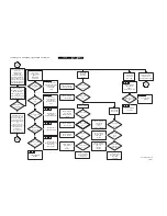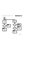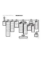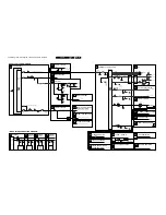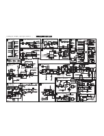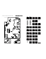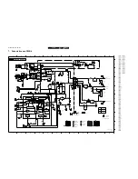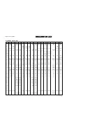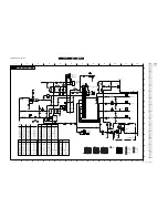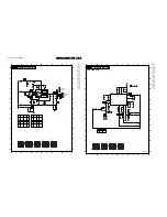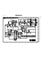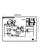
Faultfinding trees, blockdiagram, supply diagram and testpoints.
GB 15
L9.2E
6.
6.
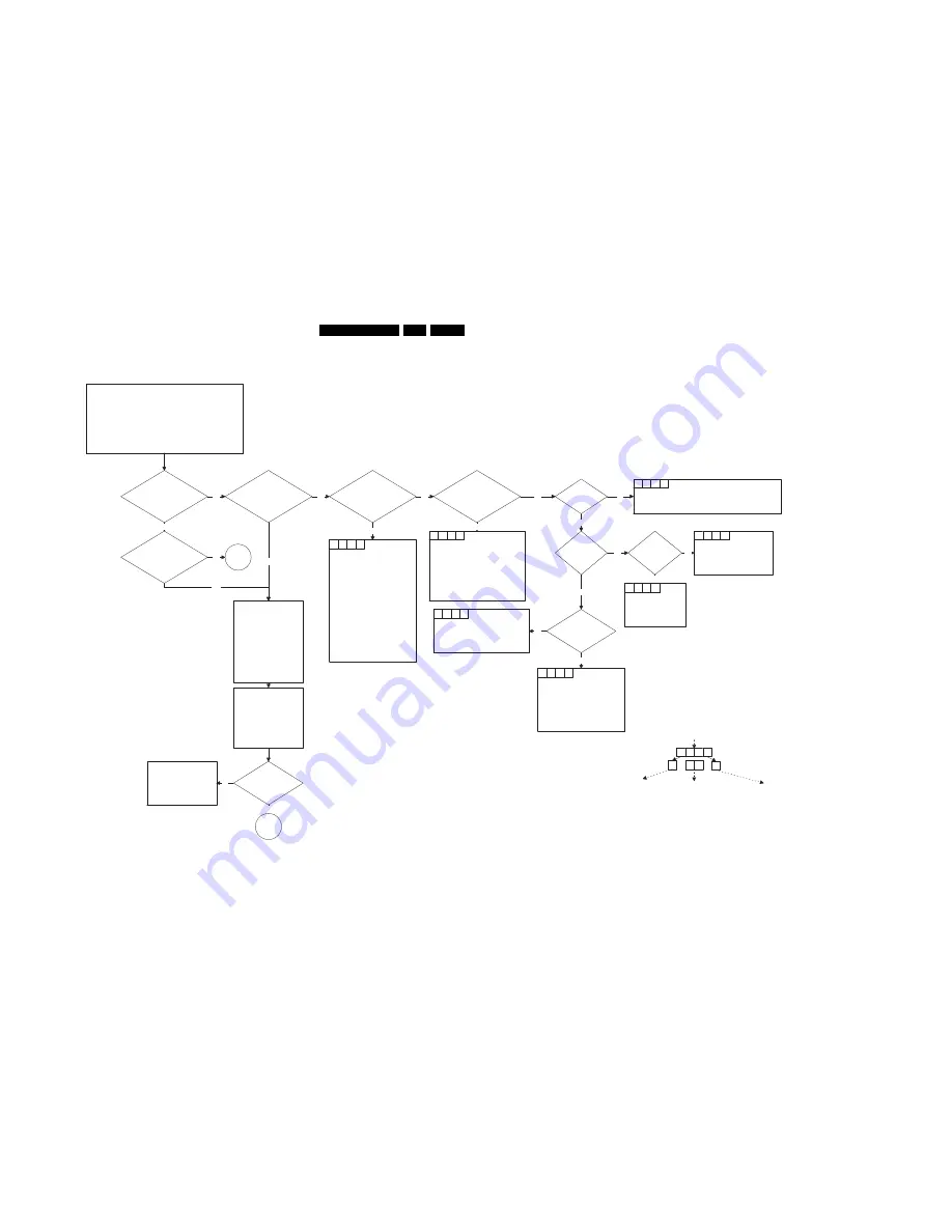
Faultfinding trees, blockdiagram, supply diagram and testpoints.
START
Connect a pattern generator to the arial input.
Set Patt.gen. to 475,25 MHz, colourbar, stereosound,
PAL B/G (for France SECAM l).
Put the Mainsswitch : on.
In normal conditions the set will start with the Red LED
blinking for one second in full intensity, one time then
after a few seconds more in half intensity while the
picture and sound will appear.
Does the red LED
blink for one second in
full intensity, one time
?
Do picture and sound
appear properly
?
Does the red LED
light in full intensity
continuously
?
Yes
Is the Power supply
hicking ?
Yes
No
No
(A1); <P1>
present?
Check/Replace
(A1); SW0231,F1500,D6502,D6503,D6504,D6505
Note: If F1500 is defective, then also check R3504
(A1); <P2>
startpuls
present?
No
No
Yes
Check/Replace
(A1); TS7518,L5552
Any secondary
voltage present ?
No
Yes
Check/Replace
(A1); IC7520
R3525
(A1);<P3>
Voltage
present?
Check/Replace
(A1); D6540,C2540,D6510,
R3510,R3529
No
No
Yes
The load of the power supply
is too high.
Isolate each branch of the load
one by one, until the hicking
disappear.
Continue with the fault finding
for the branch, which causes
the overload.
The branches are:
(A1); AudioSupply
+VBATT
MainSupply
Vaux
Yes
Check
(A7); <C1>,<C4(reset)>
3V3,
Check/Replace
TS7602,TS7605
IC7600
X1600
(A8);LED6690
Yes
A
No
(A1); voltage on
TR5545 pin9
present ?
No
Check/Replace
(A1); L5540,D6540,C2540
Yes
Note 2:
(A1) means Drawing A1
<P1> means Test point P1
1
1
1
A
Note 1:
IRIS SYMPTOM CODE
1
1
1
A
Condition
code
Main symptom
code
Extended symptom
code
1
1
1
1
B
Is there an error
indication ?
Ensure communication
with the RC,
Check/Replace
(A8);IC7680
Put the set into the
Service Default Mode
either via the DST or by
pressing the buttons on
the RC in the following
order :062596<MENU>,
or via the service pins
Yes
Set is OK
Check / correct Options
list via CSM see
chapter 5.5 of this
manual for details
No
Yes
An error code is
indicated by the blinking
LED via the SDM.
n-times blinking means
error n.
See also chapter 5.5 for
detailled information
1
1
1
D
1
1
7
3
1
1
1
1
1
1
1
A
1
1
1
1
1
1
1
A
Remark :
In normal operation the
Red LED lights in half
intensity and in
standby-mode the LED
lights in full intensity
CL 96532028_009.eps
290399
Содержание L9.2EAA
Страница 5: ...Directions for use GB 5 L9 2E 3 3 Directions for use ...
Страница 6: ...Directions for use GB 6 L9 2E 3 ...
Страница 7: ...Directions for use GB 7 L9 2E 3 ...
Страница 31: ...Schematics and PWB s GB 31 L9 2E 7 ...
Страница 32: ...Schematics and PWB s GB 32 L9 2E 7 ...
Страница 38: ...Schematics and PWB s GB 38 L9 2E 7 ...
Страница 42: ...Schematics and PWB s GB 42 L9 2E 7 Personal notes Personal notes ...


