Service Modes, fault finding and repair tips
GB 12
L9.2E
5.
Bimos start-up register is corrupted or the I2C line to the
Bimos is always low or no supply at pin 12 of the Bimos).
This error is usually detected during start-up and hence will
prevent the set from starting up.
g.
Error 6 = Bimos (TDA884x ) I2C error
Note that this error may also be reported as a result of error
codes 4 (in that case the Bimos might not be the actual
problem)
h.
Error 7 = General I2C error. This will occur in the following
cases:
SCL or SDA is shorted to ground
SCL is shorted to SDA
SDA or SCL connection at the micro controller is open
circuit.
i.
Error 8 = Microprocessor ( IC7600 ) internal RAM error ( A7
)
The micro controller internal RAM test indicated an error of
the micro controller internal memory (tested during start-
up);
j.
Error 9 = EEPROM Configuration error ( Checksum error );
EEPROM is corrupted.
k.
Error 10 = I2C error EEPROM . NV memory (EEPROM)
does not respond to the micro controller
l.
Error 11 = I2C error PLL tuner. Tuner is corrupted or the
I2C line to the Tuner is low or no supply voltage present at
pin 9, pin 6 or pin 7 of the tuner.
m. Error 12 = Black current loop instability protection. The
black current could not be stabilised. The possible cause
could be a defect in one or more of the RGB amplifiers,
RGB guns or RGB driving signals.
5.5
The "blinking LED" procedure
The contents of the error buffer can also be made visible
through the "blinking LED" procedure. This is especially useful
when there is no picture. There are two methods:
•
When the SDM is entered, the LED will blink the number of
times, equal to the value of the last (newest) error code
(repeatedly).
•
With the DST all error codes in the error buffer can be
made visible. Transmit the command: "DIAGNOSE x OK"
where x is the position in the error buffer to be made visible
x ranges from 1, (the last (actual) error) to 5 (the first error).
The LED will operate in the same way as in point 1, but now
for the error code on position x.
Example:
Error code position1 2 3 4 5
Error buffer:8 9 5 0 0
•
after entering SDM: blink (8x) - pause - blink (8x) - etc.
•
after transmitting "DIAGNOSE- 2- OK" with the DST blink
(9x) - pause - blink (9x) - etc.
•
after transmitting "DIAGNOSE- 3- OK" with the DST
blink(5x) - pause - blink(5x) - etc.
•
after transmitting "DIAGNOSE- 4- OK" with the DST
nothing happens
5.6
TROUBLE SHOOTING TIPS
In this paragraph some trouble shooting tips for the deflection
and power supply circuitry are described. For detailed
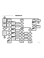
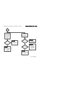
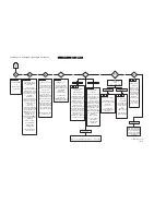
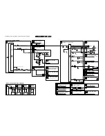
diagnostics, check the fault finding tree or use COMPAIR.
5.6.1
THE DEFLECTION CIRCUIT:
1.
Measure the +VBATT ( 95V) is present across 2551 ( A2 -
Line deflection ). If the voltage is not present, disconnect
coil 5551. (Horizontal deflection stage is disconnected). If
the voltage is present then the problem might be caused by
the deflection circuit. Possibilities:
•
Transistor 7402 is faulty
•
The driver circuit around transistor 7400 is faulty
•
No horizontal drive signal coming from the BIMOS
7250-D pin 40 ( A4 - Synchronisation )
•
Timer-IC 7607 or transitor 7608 is defect ( A7 -
Control )
2.
Note: If the Collector of 7402 is shorted to the Emitter, hick-
up noise can be heard from the power supplyIn this case
the E/W protection is disabled.is correctly working ( a
parabolic picture )
3.
Also take note of protection circuits in the line output stage.
If any of these circuits are activated, the set will shut down.
Depending on the protection, the led will blink according to
the fault defined. In order to determine which protection
circuit is active, isolation of each separate circuit is
necessary. These protection circuits are:
•
High beam current protection ( LED blinks repetitively
2 times ) - CRT panel ( B )
•
Vertical protection ( LED blinks repetitively 3 times ) -
Vertical deflection ( A3 )
5.6.2
THE POWER SUPPLY
To trouble shoot the L9 SMPS, first check the Vaux voltage on
C2561. If this voltage is not present, check fuse F1572 and
D6560. If F1572 or D6560 is not open circuit, the problem might
be caused on the primary side of the switching supply. Check
the output of the bridge rectifier on C2508 for approximately
300V DC at an input voltage of 230Vac. If this voltage is
missing, check the bridge diodes 6502 .. 6505 and the fuse
1500. If fuse F1500 is found open, check MOSFET 7518 to
make sure that there is no short circuit present and check
R3518. If the 300V DC is present on C2508, check for a start-
up voltage of approx. 13V on pin 1 of IC7520. If no start-up
voltage is present, check if R3510 is open or zener 6510 is a
short-circuit. It is necessary to have a feedback signal from the
hot primary side of switch mode transformer T5545 at pin 1 and
pin 2 for the power supply to oscillate. If the start-up voltage of
13V is present on pin 1 of IC7520 and the supply is not
oscillating, check R3529 and D6540.
Check for a drive signal at the gate of MOSFET 7518, square
wave signal - P1. Check pin 3 of IC7520 and R3525.
To determined whether OVP is active, check the presence of
Vaux at C2561.
5.6.3
Customer Service Mode (CSM)
All L9 sets are equipped with the "Customer Service Mode"
(CSM). CSM is a special service mode that can be activated
and deactivated by the customer, upon request of the service
technician/dealer during a telephone conversation in order to
identify the status of the set. This CSM is a 'read only' mode,
therefore modifications in this mode are not possible.
Entering the Customer Service Mode. The Customer Service
Mode can be switched on by pressing simultaneously the
button (MUTE) on the remote control and any key on the
control buttons (P+, P-, VOL +, VOL -) on the TV for at least 4
seconds.
When the CSM is activated:
•
picture and sound settings are set to nominal levels
•
"Service unfriendly modes" are ignored
Exit the Customer Service Mode.
The Customer Service Mode will switch off after:
•
pressing any key on the remote control handset (except
"P+" or "P-")
•
switching off the TV set with the mains switch.
All settings that were changed at activation of CSM are set
back to the initial values
5.6.4
The Customer Service Mode information screen
The following information is displayed on screen:
Содержание L9.2EAA
Страница 5: ...Directions for use GB 5 L9 2E 3 3 Directions for use ...
Страница 6: ...Directions for use GB 6 L9 2E 3 ...
Страница 7: ...Directions for use GB 7 L9 2E 3 ...
Страница 31: ...Schematics and PWB s GB 31 L9 2E 7 ...
Страница 32: ...Schematics and PWB s GB 32 L9 2E 7 ...
Страница 38: ...Schematics and PWB s GB 38 L9 2E 7 ...
Страница 42: ...Schematics and PWB s GB 42 L9 2E 7 Personal notes Personal notes ...


