Alignments
GB 43
L9.2E
8.
8.
Alignments
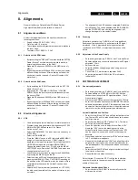
General: the Service Default Mode (SDM) and Service
Alignment Mode (SAM) are described in chapter 5.
8.1
Alignment conditions
All electrical adjustments should be performed under the
following conditions:
•
Supply voltage : 220V - 240V ( 10% )
•
Warm-up time: 10 minutes
•
The voltages and oscillograms are measured in relation to
the tuner earth.
•
Test probe: Ri > 10M
Ω
Ci < 2,5 pF.
8.1.1
Selection of the SDM-menu
•
By transmitting the "DEFAULT" command with the RC7150
Dealer Service Tool (this works both while the set is in
normal operation mode or in the SAM)
•
Standard RC sequence 062596 ( within OSD time-out )
MENU
•
By shorting test-point 0228 and 0224 on the mono-carrier
while switching on the set. After switching on the set the
short-circuit can be removed. ( Caution!! Override of 5V
protections ).
8.1.2
Selection of the SAM-menu
•
By transmitting the "ALIGN" command with the RC7150
Dealer Service Tool
•
By pressing the "CHANNEL DOWN" and "VOLUME
DOWN" key on the local keyboard simultaneously when
the set is in SDM
•
Standard RC sequence 062596 ( within OSD time-out )
OSD
•
By shorting test-point 0225 and 0226 on the mono-carrier
while switching on the set. After switching on the set the
short-circuit can be removed. ( Caution!! Override of 5V
protections ).
8.2
Electrical Alignments
8.2.1
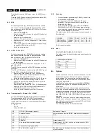
VG2
•
Use a pattern generator to display a normal black picture.
•
Program the pattern generator with a frequency of 475.25
MHz for PAL/SECAM and select L' for France
•
Switch on the TV set.
•
Select the SDM-MENU. The tuner is set to a frequency of
475.25 MHz.
•
Select the" SAM-MENU".
•
Press the "MENU" key on the RC to leave the SAM-MENU
and go to the normal user menu ( "SAM" remains
displayed at the top of the screen). Select with the MENU
UP/DOWN command the sub-menu BRIGHTNESS.
Change the default value from 31 to 50 with the MENU
LEFT/RIGHT keys. Select the CONTRAST sub-menu and
change the value from 31 to 0.
•
Leave the normal user menu to return to the SAM-MENU,
by pressing the MENU key on the RC.
•
Select sub-menu VSD and change the value from 0 to 1 by
pressing the MENU LEFT key. CAUTION!! Depending on
the position of the VG2 potentio-meter, the screen will turn
completely black because the Vertical Scan has been
disabled.
•
Adjust with VG2 potentiometer (positioned at LOT 5545)
the blue line at the middle of the screen till this line is just
not visible.
•
The alignment of the VG2 has been completed; Switch the
set to Standby. The values adapted at the BRIGHTNESS-
and the CONTRAST-menu during the alignment, will
change back again to their default values.
8.2.2
Focusing
Set pattern generator (e.g. PM5418) with Circle and Small
Squares pattern and connect to aerial input with RF signal
amplitude - 10mv. Adjusted with focusing potentiometer
(positioned at LOT 5545 ) for maximum sharpness of the
picture.
8.2.3
Adjustment of the Power Supply
•
Set pattern generator (e.g. PM5418) with Circle and Small
Squares pattern and connect to aerial input with RF signal
amplitude - 10mv.
•
Switch on the set.
•
Select the 300Vdc voltage range when using a normal
multi-meter.
•
Connect the DC multi-meter to capacitor 2409.
•
Adjust potentiometer R3540 till the DC multi-meter
indicates 95V.
8.3
SOFTWARE ADJUSTMENT
8.3.1
Geometry adjustments
•
Set pattern generator (e.g. PM5418) with Circle and Small
Squares pattern on 475.25 MHz for PAL/SECAM and
connect to aerial input with RF signal amplitude - 10mV,
France select L'-signal.
•
First enter the SDM mode to set the tuner at 475.25 MHz.
•
Enter the SAM mode and then select GEOMETRY with the
up/down keys buttons on the RC the respective items can
be selected. Use the left/right buttons to adjust the selected
items to correct the picture geometry as stated below.
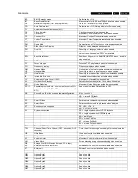
Vertical Amplitude and Position
•
Select Vertical Slope "VSL" and shift the test pattern to the
top. The text VSL and its value should be above the upper
half of the screen
•
Select Service Blanking "SBL" and set it to 1. The lower
half of the picture will be blanked.
•
Press the up button once to select Vertical Slope "VSL".
Now align "VSL" to start the blanking exactly at the
horizontal white line at the centre of the test circle. "VSL"
has the correct value now and should not be changed
anymore.
•
Press the down button once to select "SBL" and set it back
to 0. The full picture reappears.
•
Now select Vertical Amplitude "VAM" and align the picture
height to the top of the screen, so that the top horizontal
line just disappears. This corresponds with an over scan of
approx. 6%.
•
Select Vertical Shift "VSH" and align for vertical centring of
the picture on the screen.
•
Repeat the last two steps if necessary.
Select Vertical S-correction "VSC" to align the top/bottom
squares till they have the same size as the squares in the
middle of the screen.
Horizontal Amplitude and Phase
•
Select Horizontal Shift "HSH" to horizontally centre the
picture on the screen
Содержание L9.2EAA
Страница 5: ...Directions for use GB 5 L9 2E 3 3 Directions for use ...
Страница 6: ...Directions for use GB 6 L9 2E 3 ...
Страница 7: ...Directions for use GB 7 L9 2E 3 ...
Страница 31: ...Schematics and PWB s GB 31 L9 2E 7 ...
Страница 32: ...Schematics and PWB s GB 32 L9 2E 7 ...
Страница 38: ...Schematics and PWB s GB 38 L9 2E 7 ...
Страница 42: ...Schematics and PWB s GB 42 L9 2E 7 Personal notes Personal notes ...

