Adjustment
98
108-155
13
.39
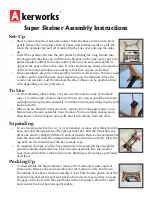
Adjusting the loading cylinder
Requirement
1. The bottom edge of the case of loading cylinder
1
should be positioned
6 mm
below
the bracket.
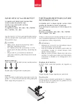
2. When the loading cylinder
1
is lowered, the upper edge of the button holder
5
should
be positioned
0.5 mm
below the button clamp.
●
Adjust loading cylinder
1
(nut
2
) in accordance with
requirement 1
.
●
Lower the loading cylinder
1
using parameter "616" (value "4").
●
Turn nut
3
(nut
4
) in accordance with
requirement 2
.
Following this adjustment, without switching off the machine or
disconnecting it from the pneumatic system, the adjustment as described in
Chapter 13.38 Setting the discharge position on the button clamp
must be
carried out with the same parameters.
108-079
1
2
6 mm
4
3
5
Fig. 13 - 37
108-080
0,5 mm
5
Содержание 3307-1 SERIES
Страница 127: ...127 Circuit diagrams Version 13 11 06 91 191 512 95 Teil 1...
Страница 128: ...128 Circuit diagrams Version 13 11 06 91 191 512 95 Teil 2...
Страница 129: ...129 91 191 512 95 Teil 3 Version 13 11 06 Circuit diagrams...
Страница 130: ...130 Circuit diagrams Version 13 11 06 91 191 512 95 Teil 4...
Страница 131: ...131 91 191 512 95 Teil 5 Version 13 11 06 Circuit diagrams...