Assembly and Operation Manual
26
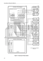
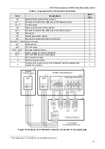
As a matter of convenience, inputs and outputs of the built-in ACS controller may be
connected not to the DIN rail contacts, as shown in the layout (Fig. 17), but directly to the
corresponding contacts of the control board (
X2
and
X3
connectors, Fig. 6). Connection
layout variant is shown in Fig. 18 .
Note:
It is recommended to install the ACS controller
Ethernet
connector so it is faced in the
direction of the sliding panel motor drive, to ensure more convenient access to it in the
future.
Use double-sided tape to secure the readers. Carefully route the cables from the readers to
the ACS controller (to the cable entry point from the ACS controller), by using the standard
gaps in parts of the section housing. Use self-adhesive pads and cable ties to secure the
cables.
Attention!
Do not route the connecting cables and wiring through the speed gate operating
mechanism inside the housing of the section in order to avoid its failure!
19. Check that all electrical connections are correct and safe.
20. Check that the jumpers and switches on the speed gate control board are set correctly (see
section 5.2.4). Set the speed gate operating mode (
pulse
or
potential
) by using the
Pulse
switch located on the control board, and set the speed gate operating mode (
normally open
or
normally closed
) by using
XP2 (Mode1)
jumper.
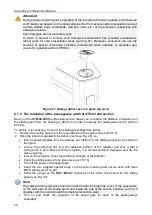
21. Unpack the sliding panels (1), filling glass (2), section glass covers (3), central inserts (4) and
side panels (6) (boxes No.2, No.4).
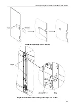
22. Assemble the parts of all sections in the following order (see sect. 8.7):
•
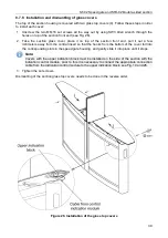
Install the front end panels (7) (see sect.8.7.1 , Fig. 19). The panel with the front end
indication block (8) must be mounted on the side of the section with the indication control
module, and the corresponding connection cable must connect the indication control
module and the front end indication block (see Fig. 19). The connection cable connected
to the
ARROW
connector of the indication control module will activate the white arrow
on the front end indication block. The cable connected to the
CROSS
connector will
activate the red cross.
•
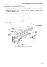
Mount the central insert (4) (see sect.8.7.4, Fig. 22 ).
•
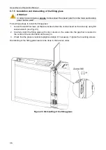
Mount the filling glass (2) (see sec.8.7.5, Fig. 23).
•
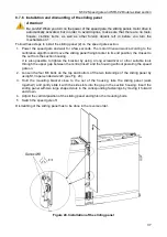
Mount the sliding panels (1) (see sec.8.7.6, Fig. 24).
Note:
If needed, reduce the distance of the sliding panel departure from the housing of the
STD-02.900
double-sided section (for arrangement of the passageway with a width of 600
mm on one side), it is necessary to mount the sliding panel departure limiter and install a
jumper on the sliding panels motor drive board (see section.8.7.9).
•
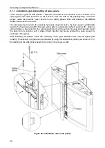
Install the side panels (6) (see sect. 8.7.7, Fig. 25).
•
Mount the glass top covers (3) (see sect. 8.7.8, Fig. 26), the cover with the upper
indication block (5) must be mounted on the side of the section with the indication control
module, prior to that it is necessary to connect the appropriate connection cable from the
indication control module to the upper indication block (see Fig. 19).
23. Test each passageway of the speed gate according to sec.9.1.
24. Check the operation of all passage lanes of the speed gate by sending control commands
from the RC-panel (see section.9.2, 9.3).
The speed gate is ready for operation after finishing installation and test procedures.
Содержание ST-02 Series
Страница 1: ...CERTIFICATE ST 02 Speed Gate STD 02 and Double Sided Section ...
Страница 2: ...ST 02 Speed gate and STD 02 Double sided section Assembly and Operation Manual ...
Страница 31: ...Assembly and Operation Manual 30 Figure 17 Speed gate wiring diagram ...
Страница 49: ...www perco com ...


