ST-02 Speed gate and STD-02 Double-sided section
11
The type of front end indication is selected during the speed gate installation by switching the
connection cable of the front end indication block to the corresponding connector of the indication
control module (located under the speed gate top cover inside the housing, Fig. 19). By default, the
connection cable is connected to the
ARROW
connector, which corresponds to the white arrow. It
is necessary to remove the glass cover (3) in order to access the indication control module (see
Fig. 26).
5.2.3 RC-panel
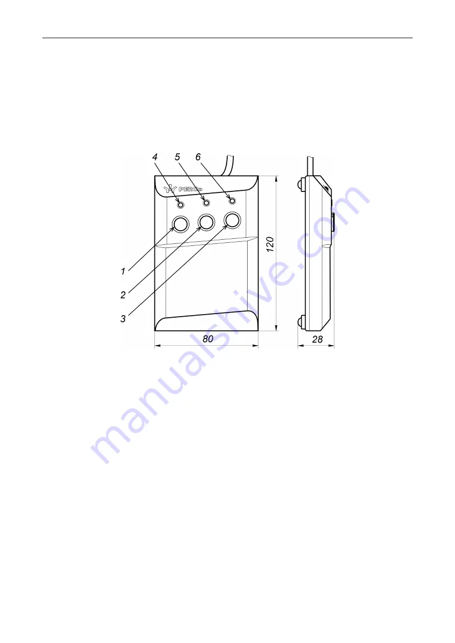
The RC-panel (11) is a small desktop device packed in a housing made of impact-resistant ABS
plastic. The RC-panel is designed to send commands by an operator when controlling the speed
gate manually. Overall view of the RC-panel is shown in Fig. 5.
Figure 5. Overall view and overall dimensions of the RC-panel
1, 2, 3 –
LEFT
,
STOP
,
RIGHT
buttons are used for control commands;
4, 6 –
"Left"
,
"Right"
green LED indicators; 5 –
"Stop"
red LED indicator
There are three buttons for sending commands on the RC-panel front panel. The middle
STOP
button is used to send the
"Passage denial"
command. Left and right buttons
LEFT
,
RIGHT
are
used to send the command to open the passage in the selected direction. LED indicators of the
passage direction status are located above the buttons. The red
"STOP"
indicator signifies that
both directions of the passage are closed. The list of control commands and RC-panel indication
for pulse and potential control modes are shown in Table 5 and Table 6.
5.2.4 Control board
The speed gate control board (Fig. 6) is located in one of the openings of the housing under the
glass top cover of the
Master
section (see Fig. 20), the Board is covered by a metal cover with four
screws with the aim of protecting from external actions. All input and output signals of the control
board, with the exception of relay outputs that control additional remote indicators (
X4
connector),
are brought out to the contacts of the remote terminal block with DIN-rail (Fig. 7, sect.5.2.5).
The control board is equipped with a microcontroller that processes incoming (
Unlock A
,
Stop
,
Unlock B
and
Fire Alarm
) control commands, monitors the optical sensors status and, based on
the received data, generates commands for the sliding panels motor drive.
Also, the microcontroller generates signals on the outputs of the control board: for RC-panel
indication (outputs
Led A
,
Led Stop
and
Led B
), for remote indication (outputs
Light A
,
Light B
), the
registration of the passage in the corresponding direction (
PASS A
and
PASS B
), the alarm
(
Alarm
). Elements of the control board:
Содержание ST-02 Series
Страница 1: ...CERTIFICATE ST 02 Speed Gate STD 02 and Double Sided Section ...
Страница 2: ...ST 02 Speed gate and STD 02 Double sided section Assembly and Operation Manual ...
Страница 31: ...Assembly and Operation Manual 30 Figure 17 Speed gate wiring diagram ...
Страница 49: ...www perco com ...


