Assembly and Operation Manual
14
The
Slave
section uses a similar remote terminal block to connect the power and motor drive
control cables DC (9) and CAN (10), as well as, if necessary, the connection cable for the built-in
reader.
Also, there are unused and unnumbered contacts on the DIN-rail, in addition to those listed in the
table, that can be used to connect other additional devices to the speed gate.
5.2.6 Control signals parameters
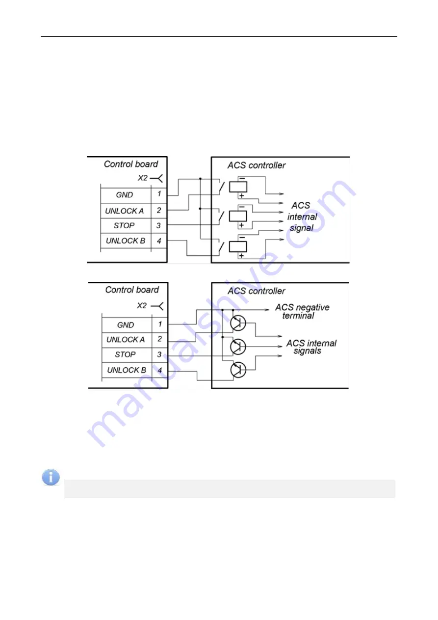
Passage control through the speed gate is carried out by sending control signals to the
Unlock A
,
Stop
and
Unlock B
inputs. The control signal is a
low-level signal
at the
Unlock A
,
Stop
and
Unlock B
contacts relative to the
GND
contact. Normally open relay contact or circuit with open-
collector output can serve as a control element (Fig. 8 and 9).
Figure 8. Control elements of the external device – normally opened relay contact
Figure 9. Control elements of the external device – a circuit with open-collector output
Emergency opening of the speed gate is carried out by sending a control signal to the
Fire Alarm
input.
The control signal is a
low-level signal released
from the
Fire Alarm
contact relative to the
GND
contact. Normally closed relay contact or circuit with open-collector output can serve as a
control element. All control commands sent to the other inputs of the speed gate are ignored.
When a low-level signal is sent to the
Fire Alarm
input, the
"Passage denial"
command is
automatically sent and the speed gate sliding panels will close (see section 5.3.2).
Note:
In order to generate a high-level signal at all input contacts (
Unlock A
,
Stop
,
Unlock B
,
Fire Alarm
) it is necessary to use
1kOhm
resistors connected to the
+ 3.3 V
power bus.
The control element must provide the following signal characteristics:
control element-relay contact:
minimum commutated current ............................................................................... max. 4
mA
closed contact resistance
(with the account for the resistance of the connection cable ........................... max. 200
Ohm
control element-circuit with open collector output:
voltage at closed contact (low-level
signal, at the control board input) ................................................................................... max. 0.8
V
Содержание ST-02 Series
Страница 1: ...CERTIFICATE ST 02 Speed Gate STD 02 and Double Sided Section ...
Страница 2: ...ST 02 Speed gate and STD 02 Double sided section Assembly and Operation Manual ...
Страница 31: ...Assembly and Operation Manual 30 Figure 17 Speed gate wiring diagram ...
Страница 49: ...www perco com ...


