Assembly and Operation Manual
20
5.4.2 Siren
The siren is connected to the
ALARM
relay output of the control board via
ALARM 1
,
ALARM 2
,
GND
and
+ 12V
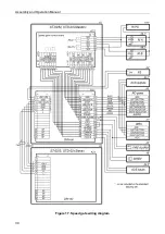
contacts of the remote terminal block in accordance with the speed gate wiring
diagram (Fig. 17)
.
The voltage is not supplied on the relay coil in the normalized state, the relay contacts are opened.
The output is activated by the passage sensors during an unauthorized passage attempt, as well
as during switching to
"Alarm"
mode (see section 9.4). When the voltage is supplied to the relay
coil, the relay contacts close. The fact of supplying voltage to the relay coil can be determined by
the red LED on the control board near the corresponding relay (the jumper has to be installed on
the
XP3 (+12V)
connector of the control board).
Output stage - relay contacts (Fig. 3) with the following signal characteristics:
maximum commutating voltage ............................................................................... 42
V
DC
maximum commutated current ................................................................................ 0.25 mA
closed contact resistance .......................................................................... max. 0.15 Ohms
The maximum current consumption of the siren when it is connected to
+ 12V
contact of remote
terminal block should not exceed 0.3 A.
5.4.3 Remote indication blocks
Remote indication blocks for the corresponding passage directions are connected to
LIGHT A
and
LIGHT B
outputs
.
The outputs feature a complete set of contacts:
NO
normally open,
NC
normally
closed and
C
common outputs. Connection to the outputs should be performed via corresponding
contacts of the remote terminal block.
While passage granting indication in direction A / B is on, the LIGHT
A
/
LIGHT
B
relay of the
corresponding direction is activated (the coil is energized), and normalized upon passage denial
indication. The fact of power supply to the relay coil can be determined by the active red LED on
the control board located by the corresponding relay.
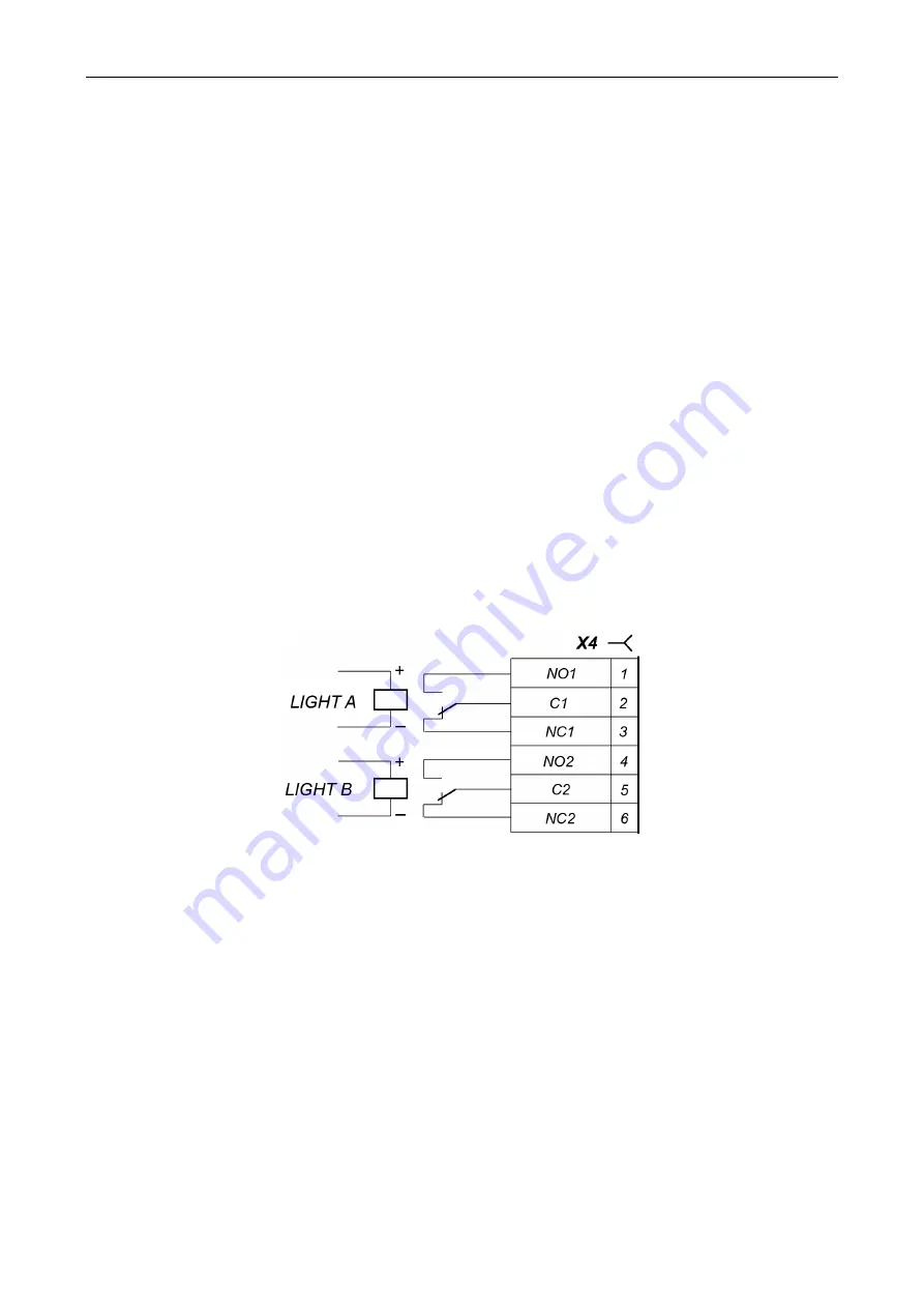
Figure 12. Output stages for Light A and Light B
Output stages for
LIGHT A
and
LIGHT B
–
relay changeover contacts (see Fig. 4) with the
following signal characteristics:
maximum commutating voltage .............................................................................. 30
V DC
maximum commutating voltage .............................................................................. 42
V AC
maximum commutating current .......................................................................... 3
A DC / AC
resistance of the closed contact ................................................................. max. 0.15
Ohms
6 MARKING AND PACKAGING
Each speed gate section features a marking sticker on the internal surface of the section under the
side panel (6) (see Fig. 3 and 4). The sticker contains: trademark and contact details of the
manufacturer, section name and serial number of the product, date of manufacture, supply voltage
and power consumption. There are also stickers that indicate the side of the section (
Master
or
Slave
) in
STD-02
double-sided section, located under the side panels.
Also, the
Master
section and the double-sided section have a sticker located on the inner surface
of the side panel (6). The label contains a wiring diagram that is similar to that shown in Fig. 17.
Содержание ST-02 Series
Страница 1: ...CERTIFICATE ST 02 Speed Gate STD 02 and Double Sided Section ...
Страница 2: ...ST 02 Speed gate and STD 02 Double sided section Assembly and Operation Manual ...
Страница 31: ...Assembly and Operation Manual 30 Figure 17 Speed gate wiring diagram ...
Страница 49: ...www perco com ...


