Assembly and Operation Manual
44
Table 6. Potential control mode (Pulse switch is in OFF position)
Commands
It is necessary to
ensure
Indication
Speed gate status
RC-panel
Indication
blocks
Normally
closed
mode
Normally open
mode
"Both directions
blocked»
A high level at
Unlock A
and
Unlock B
contacts
(or a low level on
the
Stop
contact)
The red
"Stop"
light
is on
The red cross
for both
directions
Sliding
panels are
closed
The sliding
panels are
opened and
close during
passage
attempt.
"Direction is
opened»
A low level at the
contact of a
specified direction.
A high level at the
rest of the contacts.
The green
indicator of
the set
direction
"Left"
or
"Right"
is on
Green arrow
for a specified
direction, red
cross for
another
direction
The sliding panels are opened
for the passage in the
specified direction
"Both directions
are opened»
A low level at
Unlock A
and
Unlock B
contacts.
A high level at the
Stop
contact
Two green
indicators
"Left"
and
"Right"
are
lit at the
same time»
Green arrow
for both
directions
The sliding panels are opened
for the passage in both
directions
9.4 Actions in case of emergency
9.4.1
"Alarm"
mode
In case when an obstacle prevents the free closing of the speed gate sliding panels, the speed
gate will automatically switch to the
"Alarm"
mode. The mode is designed to prevent the failure of
the speed gate motor drive due to overheating.
In case when an obstacle prevents the closing of the sliding panel, three attempts to close sliding
panels at intervals of 3 seconds will be made. If the obstacle is not removed, then the speed gate
will switch to the
"Alarm"
mode. In the
"Alarm"
mode, the speed gate sliding panels can be moved
apart manually, which allows you to easily remove the obstacle from the passageway. At the same
time, all three indicators of the RC-panel will flash and a continuous signal will sound.
Deactivation of the
"Alarm"
mode will be done automatically when the obstacle is removed and the
speed gate passageway is free.
9.4.2
"Fire Alarm
"
mode
In case of dangerous situations at the site, the speed gate passageway can be used as an
additional emergency exit.
It is possible to switch the speed gate to
Fire Alarm
mode by the emergency passage opening
device (fire alarm device, emergency buttons, etc.). In this mode, if the speed gate sliding panels
have been closed, then they will open and remain in this state in all operating modes for free
passage in both directions, herewith the green indicators of passage granting will flash
simultaneously in both directions, the control commands from other devices and SOFTWARE will
be ignored (see section 5.3.2).
Also, the speed gate sliding panels can be moved apart manually (not blocked) when the power
supply is removed.
Attention!
Safety evacuation exits are used for emergency evacuation of people from the territory of
the enterprise in case of fire, natural disasters and other extremal situations. For example,
BH02
anti-panic rotary section of the railing system can serve as such exit.
Содержание ST-02 Series
Страница 1: ...CERTIFICATE ST 02 Speed Gate STD 02 and Double Sided Section ...
Страница 2: ...ST 02 Speed gate and STD 02 Double sided section Assembly and Operation Manual ...
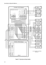
Страница 31: ...Assembly and Operation Manual 30 Figure 17 Speed gate wiring diagram ...
Страница 49: ...www perco com ...

