Assembly and Operation Manual
34
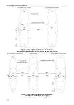
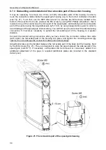
8.7.3 Dismantling and installation of the removable part of the section housing
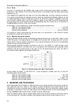
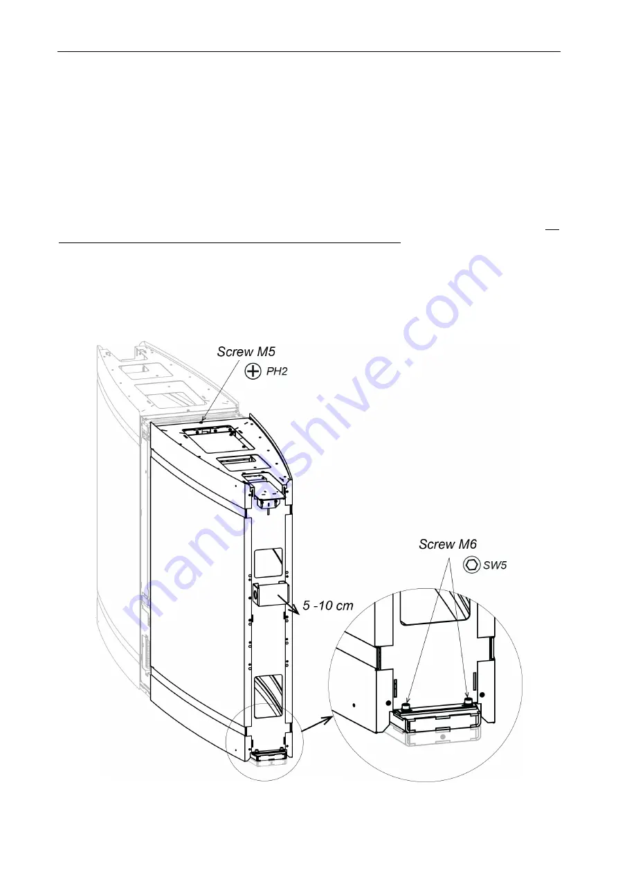
It may be necessary to remove one of two (or both) removable parts of the housing in order to
route the connection cables inside the speed gate housing (e.g. to the built-in controller or reader)
(see Fig. 21). To do this, use the SW5 Allen wrench to unscrew two M6 screws, located at the
bottom of the section front end, unscrew the M5 screw by using PH2 Phillips screwdriver, that is
located on top of the center near the drive part of the speed gate, and carefully pull the removable
part of the section along the longitudinal axis by 5-10 cm by using transportation eyelet in order to
avoid damage of the speed gate internal wiring. You will first need to disconnect the internal wiring
connectors if it becomes necessary to extend the removable part of the housing to a greater
distance.
Connect the internal wiring connectors after you have routed the connection cables, then slide
(with a jerk) the removable part of the housing into place, and tighten the mounting screws. Be
careful, do not to damage the connection cables and internal wiring!
Adjustment plates can be installed between the removable part of the body and the housing, fixed
by the M6 screws (Fig. 21). They are designed to align the gaps between the side panels of the
speed gate (sect.8.7.7). If necessary, extra plates can be removed or, conversely, added if an
additional adjustment of the gaps is required (additional plates are included in the standard
delivery set).
Figure 21. The removable part of the speed gate housing
Содержание ST-02 Series
Страница 1: ...CERTIFICATE ST 02 Speed Gate STD 02 and Double Sided Section ...
Страница 2: ...ST 02 Speed gate and STD 02 Double sided section Assembly and Operation Manual ...
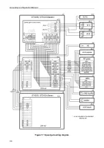
Страница 31: ...Assembly and Operation Manual 30 Figure 17 Speed gate wiring diagram ...
Страница 49: ...www perco com ...

