Assembly and Operation Manual
18
5.3.1 RC-panel connection
RC-panel is connected with a flexible multicore cable to
Unlock A
,
Stop
,
Unlock B
,
Led A
,
Led Stop
,
Led B, Sound
and
GND
contacts of the remote terminal block in accordance with the
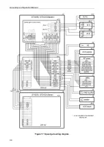
speed gate wiring diagram (see Fig. 17).
Note:
When the speed gate is operated as part of ACS, it is recommended to connect the
RC-panel to the ACS-controller in accordance with the controller operational documentation.
The WRC receiver is connected to the
Unlock A
,
Stop
,
Unlock B
and
GND
contacts of the
remote terminal block or, when installed inside the speed gate, directly to the control board
to the corresponding contacts of the
X2
connector. The power supply of the WRC-receiver is
connected to
+12V
contact of the remote terminal block or
X3
connector of the control
board.
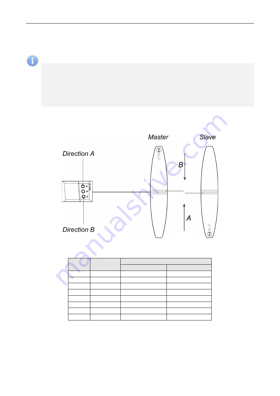
The standard position of the RC-panel towards the sections is shown in Fig.10. If the operator
working place is located on the opposite side regarding
Master
section, then for ease of operation
it is necessary to swap the wires from the RC-panel connected to the contacts
Unlock A
and
Unlock B
, as well as
Led A
and
Led B
, respectively (see Table 2).
Figure 10. Standard orientation of the RC-panel towards the speed gate sections
Table 2. Connection of the RC-panel cable to the remote terminal block
No.
Contact
The orientation of the RC-panel
Standard
Reverse
8
GND
black
black
9
Unlock A
white
green
10
Stop
blue
blue
11
Unlock B
green
white
12
Led A
yellow
red
13
Led Stop
orange
orange
14
Led B
red
yellow
15
Sound
brown
brown
5.3.2
Fire Alarm
device
Connection of the device for emergency opening of the
Fire Alarm
passage is made to the
Fire
Alarm
input (contacts of the
Fire Alarm
and
GND
of the remote terminal block) in accordance with
the speed gate wiring diagram (Fig. 17). Connection of the
Fire Alarm
device in order to control
multiple speed gates at a single checkpoint is shown in Fig. 16. A serial wiring diagram is used to
control multiple speed gates when a single
Fire Alarm
output is used.
Содержание ST-02 Series
Страница 1: ...CERTIFICATE ST 02 Speed Gate STD 02 and Double Sided Section ...
Страница 2: ...ST 02 Speed gate and STD 02 Double sided section Assembly and Operation Manual ...
Страница 31: ...Assembly and Operation Manual 30 Figure 17 Speed gate wiring diagram ...
Страница 49: ...www perco com ...


