Assembly and Operation Manual
12
Figure 6. Control board overview
Connectors for jumpers:
•
XP1 (Program)
– service connector.
•
XP2 (Mode1)
– connector for switching the speed gate in normally open mode (see section
5.2.8 ). By default, the jumper is not installed, which corresponds to the normally closed mode.
•
XP3 (+12V)
– connector for the activation of LED indication on the control board. By default,
the jumper is installed, which corresponds to the activated indication.
•
XP4 (Update)
– connector for switching the control board to firmware update mode via USB-
interface. By default, the jumper is removed.
•
XP6 (BUZZ)
– connector on the control board for buzzer activation. The buzzer duplicates the
sound indication of the RC-panel and the siren. By default, the jumper is installed, which
corresponds to the activated buzzer.
•
XP7 (Mode2)
– is not used. The jumper must be removed during operation.
Switches:
•
Pulse
– switches the speed gate to pulse control mode. By default, the switch is in the
ON
position, which corresponds to the pulse control mode of the speed gate.
•
Size1
,
Size2
-by default, both switches are set to the position corresponding to this type of
speed gate, it is forbidden to change their position during operation!
•
Test 1
- is not used. Must be in
OFF
position during operation.
•
Test 2
-is used to turn on the LED indication on the PCS boards. By default, the switch is in the
OFF
position, which corresponds to the deactivated indication.
•
R1
-is used to enable the "
Automatic opening in the selected direction
" operating mode (see
sect. 5.2.9). By default, the switch is in the
OFF
position.
•
R2
-is used to select the direction of the authorized passage in the "
Automatic opening in the selected
direction
" mode (switch
R1
in the
ON
position). By default, the switch is in the
OFF
position, which
corresponds to direction A.
5.2.5 Remote terminal block (DIN rail)
Input and output signals from the control board of the
Master
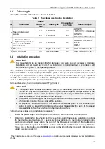
section are brought out to the
contacts of the remote terminal block (DIN-rail) (Fig. 7), which greatly simplifies the connection of
the speed gate.
The remote terminal block is located at the bottom, under the side panel of the
Master
section
(section side) on the inner side of the passageway. The appearance of the remote terminal block,
as well as the contacts numbering order, are shown in Fig. 7. The contact assignment of the
remote terminal block is shown in the Table 1.
Содержание ST-02 Series
Страница 1: ...CERTIFICATE ST 02 Speed Gate STD 02 and Double Sided Section ...
Страница 2: ...ST 02 Speed gate and STD 02 Double sided section Assembly and Operation Manual ...
Страница 31: ...Assembly and Operation Manual 30 Figure 17 Speed gate wiring diagram ...
Страница 49: ...www perco com ...


