ST-02 Speed gate and STD-02 Double-sided section
13
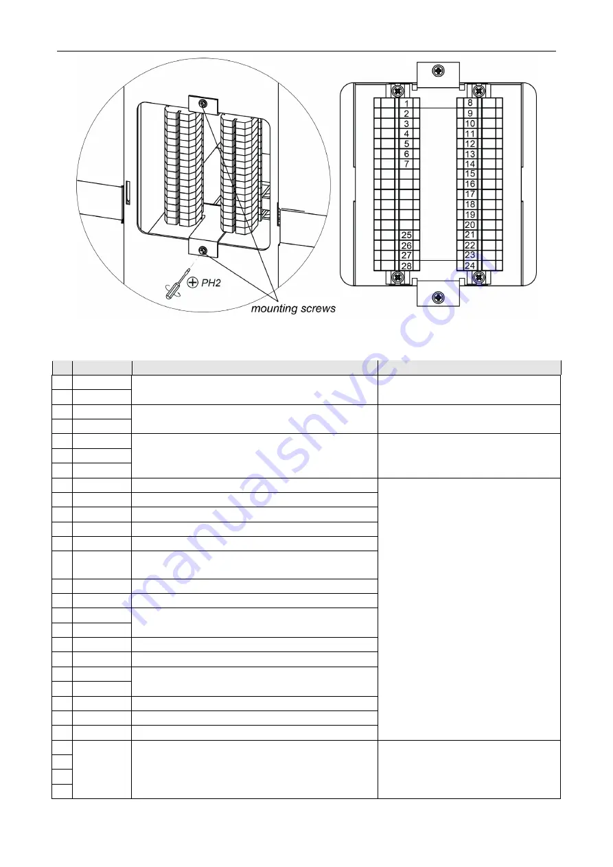
Figure 7. Overview of the remote terminal block
Table 1. Contact assignments of the remote terminal block
№
Contact
Master
section
Slave
section
1
+24V
External power supply connection
Not used
2
GND
3
+24V
Power supply of the
Slave
section (DC cable
connection)
Power supply of the
Master
section
(DC cable connection)
4
GND
5
GND
CAN cable connection
CAN cable connection
6
H
7
L
8
GND
Common (RC-panel connection)
Not installed
9
Unlock A
Control input of A direction
10
Stop
Control input – passage denial
11
Unlock B
Control input of B direction
12
Led A
Indication output of direction A on the RC-panel
13
Led Stop
Output of passage denial indication on the
RC-panel
14
Led B
Indication output of direction B on the RC-panel
15
Sound
RC-panel audio output
16
Fire Alarm
Emergency passage opening control input
17
GND
18
+12V
+12V output for additional devices
19
GND
Common
20
Alarm1
Output for the siren connection
21
Alarm2
22
Common
Common for
PASS A
,
PASS B
outputs
23
PASS A PASS A
output (passage in A direction)
24
PASS B PASS B
output (passage in B direction)
25
RF
Spare contact for built-in reader connection
Spare contact for built-in reader
connection
26
27
28
Содержание ST-02 Series
Страница 1: ...CERTIFICATE ST 02 Speed Gate STD 02 and Double Sided Section ...
Страница 2: ...ST 02 Speed gate and STD 02 Double sided section Assembly and Operation Manual ...
Страница 31: ...Assembly and Operation Manual 30 Figure 17 Speed gate wiring diagram ...
Страница 49: ...www perco com ...


