ST-02 Speed gate and STD-02 Double-sided section
17
3. The microcontroller will deactivate the alarm mode when the user leaves the passageway. The
audible alarm switches off. In the normally open operating mode, the speed gate sliding panels
will move apart and open the passageway.
In the potential control mode, the speed gate operation algorithm
depends on the external
commands of the ACS controller. For the correct speed gate operation, the passage granting
control signal from the ACS controller must be removed after receiving the signal from the
PASS
output of this direction.
5.2.9 “Automatic opening in the selected direction” mode
This is an additional speed gate operating mode that was designed to organize a special passage
mode, when it is necessary to provide free entry (or exit), in cases when the sliding panels should
be closed in the home position, and to prevent unauthorized passage in the opposite direction at
the same time (for example, at the entrance to the sales area of the store, etc.).
Attention!
"Automatic opening in the selected direction"
mode is relevant only for the normally closed
speed gate operating mode (see section 5.2.8 ).
This mode is activated by means of
R1
and
R2
switches located on the speed gate control board
(see Fig. 2, sect.5.2.4).
Attention!
Change of the switches position must be carried out only when the speed gate power is
switched off.
The mode allows you to organize free passage through the speed gate in one pre-selected
direction, with automatic opening and closing of the sliding panels when walking through. If the
passage is authorized from the opposite direction (by means of the RC-panel, WRC-device or
ACS-controller), the
"Automatic opening in the selected direction"
mode switches off during this
passage.
The speed gate operation algorithm in this mode:
1) In the initial state and unoccupied passageway in the
"Automatic opening in the selected
direction"
mode direction, the green indicator of the passage granting is lit, the red indicator of
the passage denial is lit from the opposite direction. Pressing of the RC-panel button or
sending commands from the ACS controller for passage permission in the
"Automatic opening
in the selected direction"
mode direction are ignored.
2) The passage sensors send signals to the speed gate controller to open sliding panels when
the user is walking through in the
"Automatic opening in the selected direction"
mode. The
speed gate sliding panels open for the passage in this direction, then the passage sensors
send the command to the controller to close the sliding panels after the passage, the sliding
panels automatically close behind the user. The indication remains in its initial state.
3) The speed gate operation algorithm is similar to the usual algorithm when the passage is done
in the direction that is opposite to
"Automatic opening in the selected direction"
mode
(sect.5.2.8). The
"Automatic opening in the selected direction"
mode switches off for the time
of passage (time-out period) during the authorized passage, while the
"Free passage"
mode
set for this direction – for the entire period that this mode is set to.
4) All other situations, including attempts to simultaneously pass in both directions, are
considered abnormal, the controller will generate an alarm and a command to close the sliding
panels when such situations occur.
5.3 Operating devices
The speed gate can be controlled by the following devices: The RC-panel / WRC-device, the ACS-
controller, the
Fire Alarm
device. These devices can be connected to the speed gate separately, all
together (in parallel) or in any combination with each other.
There may be cases of overlapping control signals when several control devices are connected to
the speed gate in parallel. In this case, the reaction of the speed gate will correspond to the
command formed by the combination of signals (see Appendixes 1 and 2).
Содержание ST-02 Series
Страница 1: ...CERTIFICATE ST 02 Speed Gate STD 02 and Double Sided Section ...
Страница 2: ...ST 02 Speed gate and STD 02 Double sided section Assembly and Operation Manual ...
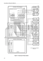
Страница 31: ...Assembly and Operation Manual 30 Figure 17 Speed gate wiring diagram ...
Страница 49: ...www perco com ...


