ST-02 Speed gate and STD-02 Double-sided section
31
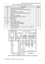
Table 4. Layout parts list of electrical connections
Item
Designation
QTY,
PCs.
A1
Master
section (side of the section)
1
A1.1
Remote terminal block (DIN rail) of the
Master
section
1
A1.2
Control board
1
A2
Slave
section (side of the section)
1
A2.1
Remote terminal block (DIN rail) of the
Slave
section
1
A3
RC-panel
1
A4
Speed gate power supply
1
A5
1
Device for sending
FireAlarm
command
1
A6
1
(A6.1, A6.2) ACS controller
1
A7
1
WRC-device
1
A8
1
12V DC siren
1
A9.1
1
, A9.2
1
Remote indication block
2
A10
1
Power supply for remote indicators
1
A11
1
RF1 and RF2 access card readers
2
1
DC connection cable
1
2
CAN connection cable
1
3
Jumper wire in case there is no
FireAlarm
device installed (A5).
Installed by default
1
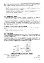
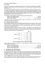
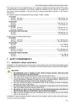
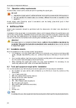
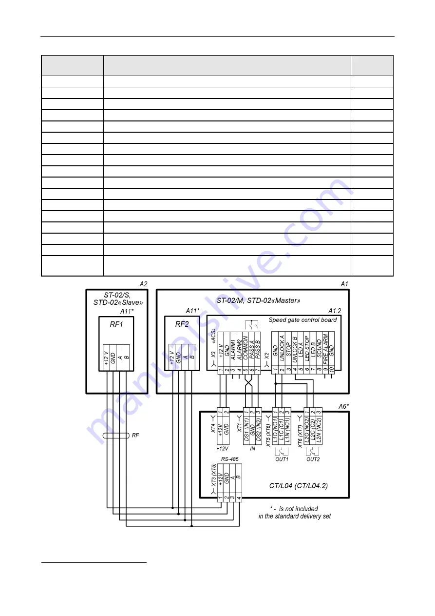
Figure 18. Example of CT/L04 ACS controller connection to the speed gate
1
The equipment is not included in the standard delivery set.
Содержание ST-02 Series
Страница 1: ...CERTIFICATE ST 02 Speed Gate STD 02 and Double Sided Section ...
Страница 2: ...ST 02 Speed gate and STD 02 Double sided section Assembly and Operation Manual ...
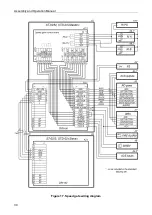
Страница 31: ...Assembly and Operation Manual 30 Figure 17 Speed gate wiring diagram ...
Страница 49: ...www perco com ...


