


26
BIOS Setup Utility
Off: Disabled this function. (Default value)
On: Set AC Loss auto restart.
Former-Sts: Set AC Loss to former-Sts.
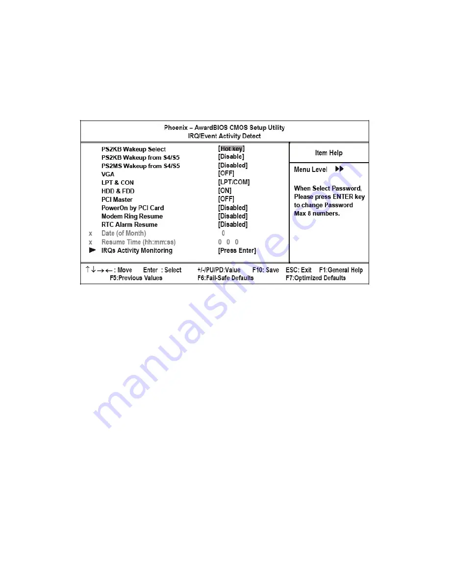
IRQ/Event Activity Detect
This item opens a submenu that enables you to set events that will resume the system from a power saving mode.
Select the item and press <Enter> to open the following menu:
Figure 2.13
IRQ/Event Activity Detect menu
PS2KB Wakeup Select
Set Hot key to wakeup PS/2 Keyboard.
PS2KB Wakeup From S4/S5
Sets a Hot Key to restore the system from the power saving mode to an active state.
Disabled: Disabled this function.(Default value)
Ctrl+F1~Ctrl+F12: Set PS/2 keyboard wakeup from S4/S5 to Ctrl+F1~Ctrl+F12.
Power: Press power key to wake PS/2 keyboard from S4/S5.
Wake: Press Wake key to wake PS/2 keyboard from S4/S5.
Any Key: Press any key to wake PS/2 keyboard from S4/S5.
PS2MS Wakeup From S4/S5
Enables any mouse activity to restore the system from the power saving mode to an active state.
Disabled: Disabled this function.(Default value)
Enabled: Enabled PS2 mouse wakeup from S4/S5.
VGA (Off)
When set to On, the system power will resume the system from a power saving mode if there is any VGA activity. The
default setting is OFF.
Содержание PT-5700
Страница 1: ...PT 5700 Service Manual...
Страница 2: ......
Страница 8: ...vi...
Страница 14: ...6 Getting Started...
Страница 42: ...34 BIOS Setup Utility...
Страница 45: ...Chipset driver 37 5 Click Next to continue 6 Select Yes I want to restart my computer now and then click Finish...
Страница 48: ...40 Installing Drivers and Software 5 Click Next to continue 6 Click Next to continue...
Страница 50: ...42 Installing Drivers and Software 4 Click Install to continue 5 Click Finish...
Страница 53: ...Touch screen driver 45 8 Click Next to continue 9 Click Next to continue...
Страница 62: ...54 Locating the Problem...
Страница 71: ...Replacing Parts 63 5 Disconnect the 2 cables 6 Remove the 3 screws M3 x 4 mm silver 7 Remove the MSR...
Страница 76: ...68 Replacing Field Replaceable Units FRUs 5 Remove the 4 screws M3 x 4 mm silver 6 Remove the mainboard...
Страница 80: ...72 Replacing Field Replaceable Units FRUs 4 Remove the waterproof seal...
Страница 86: ...78 Appendix Exploded Diagrams and Parts List Display Parts and Cables Figure 6 2 Exploded diagram cables...
Страница 88: ...80 Appendix Exploded Diagrams and Parts List...