


10
BIOS Setup Utility
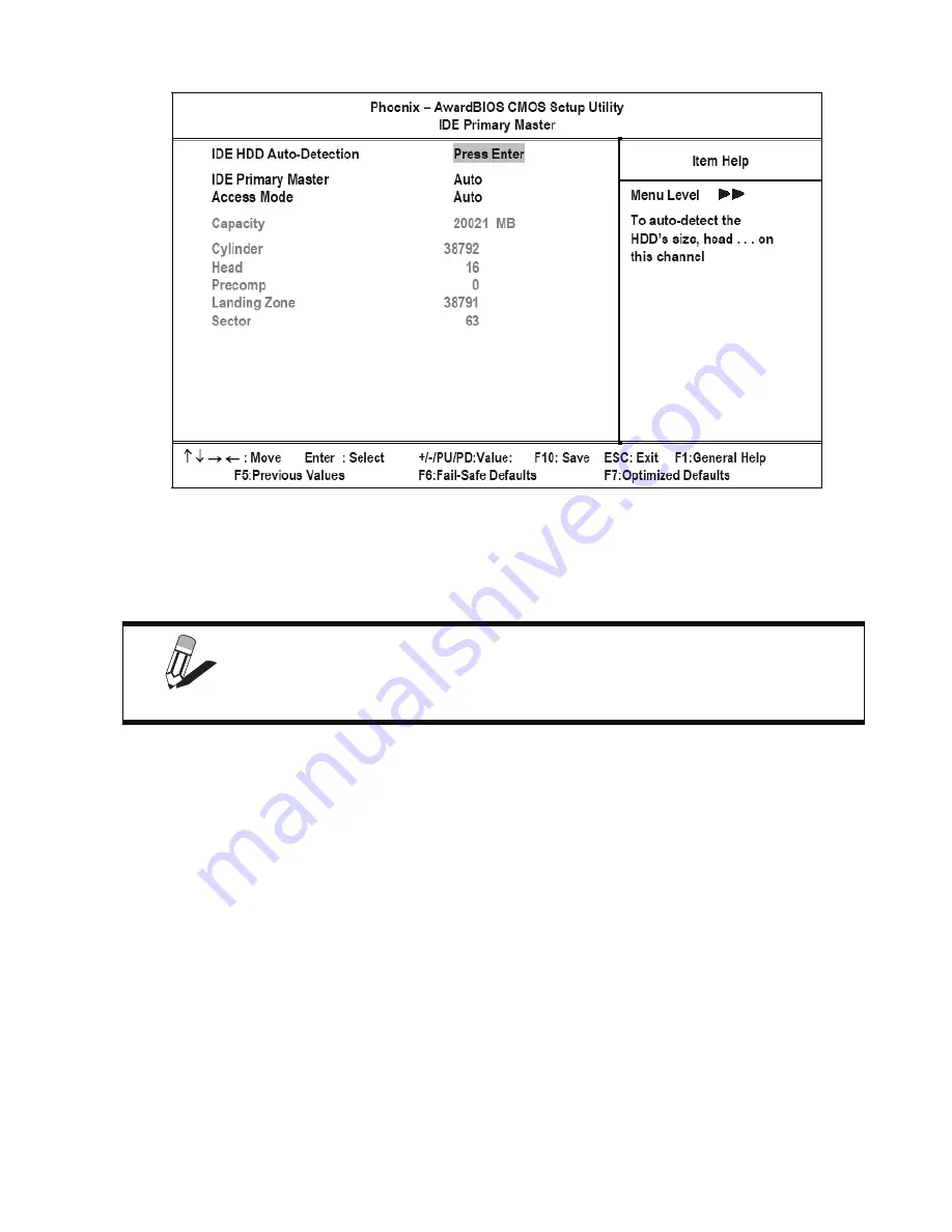
Figure 2.3
IDE Primary Master Submenu
IDE HDD Auto-Detection
Press
Enter
while this item is highlighted if you want the Setup Utility to automatically detect and configure a hard
disk drive on the IDE channel.
IDE Primary/Secondary Master/Slave
If you leave this item at
Auto
, the system will automatically detect and configure any IDE devices it finds. If it fails to
find a hard disk, change the value to
Manual
and then manually configure the drive by entering the characteristics of
the drive in the fields described below:
•
Capacity
– displays the capacity of the HDD in megabytes (MB).
•
Cylinder
– indicates the number of cylinders that the HDD has. A cylinder is the sum total of all tracks that are
in the same location on every disk surface.
•
Head
– displays the number of heads in the HDD. A head is a device that reads and writes data on the hard
disk.
•
Precomp
– displays the track where precompensation is initiated. Precompensation is a feature whereby the
HDD uses a stronger magnetic field to write data in sectors that are closer to the center of the disk. In CAV
recording, in which the disk spins at a constant speed, the sectors closest to the spindle are packed tighter than
the outer sectors.
•
Landing Zone
– displays the location of the safe non-data area on a hard disk that is used for parking the read/
write head.
•
Sector
– displays the number of sectors available on the HDD. A sector is the smallest unit of storage space on
a disk.
NOTE
If you are setting up a new hard disk drive that supports LBA mode, more than
one line will appear in the parameter box. Choose the line that lists LBA for an
LBA drive.
Содержание PT-5700
Страница 1: ...PT 5700 Service Manual...
Страница 2: ......
Страница 8: ...vi...
Страница 14: ...6 Getting Started...
Страница 42: ...34 BIOS Setup Utility...
Страница 45: ...Chipset driver 37 5 Click Next to continue 6 Select Yes I want to restart my computer now and then click Finish...
Страница 48: ...40 Installing Drivers and Software 5 Click Next to continue 6 Click Next to continue...
Страница 50: ...42 Installing Drivers and Software 4 Click Install to continue 5 Click Finish...
Страница 53: ...Touch screen driver 45 8 Click Next to continue 9 Click Next to continue...
Страница 62: ...54 Locating the Problem...
Страница 71: ...Replacing Parts 63 5 Disconnect the 2 cables 6 Remove the 3 screws M3 x 4 mm silver 7 Remove the MSR...
Страница 76: ...68 Replacing Field Replaceable Units FRUs 5 Remove the 4 screws M3 x 4 mm silver 6 Remove the mainboard...
Страница 80: ...72 Replacing Field Replaceable Units FRUs 4 Remove the waterproof seal...
Страница 86: ...78 Appendix Exploded Diagrams and Parts List Display Parts and Cables Figure 6 2 Exploded diagram cables...
Страница 88: ...80 Appendix Exploded Diagrams and Parts List...