


Integrated Peripherals
21
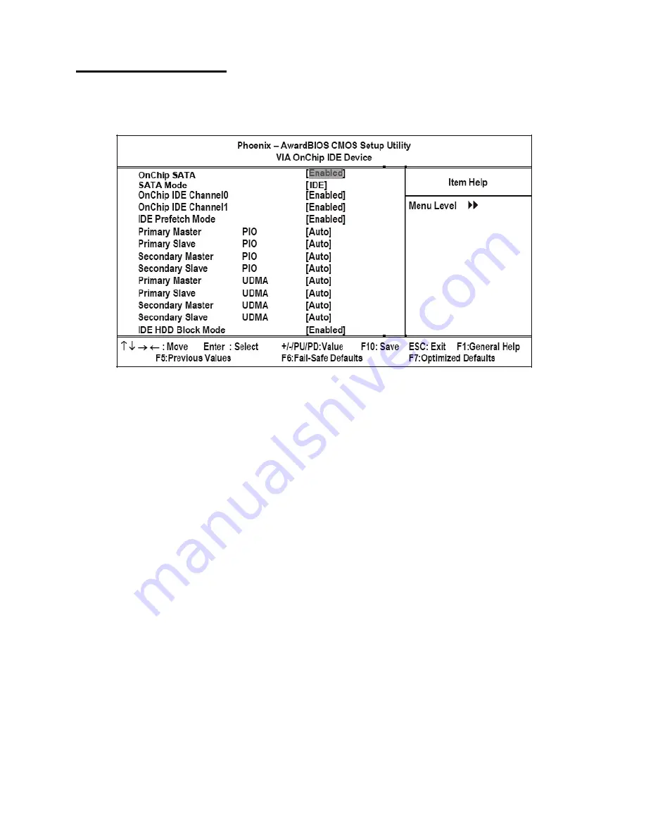
VIA OnChip IDE Device
Use this item to enable or disable the PCI IDE channels that are integrated on the mainboard. Select the item and press
<Enter> to open the following menu:
Figure 2.9
VIA OnChip IDE Device menu
On-Chip SATA
Use these items to enable or disable the PCI IDE channels that are integrated on the mainboard. The default setting for
both fields is Enabled.
SATA Mode
IDE: Select onboard Seria ATA function as IDE.(Default value)
RAID: Select onboard Seria ATA function as RAID..
OnChip IDE Channel0
Enabled: Enable onboard 1st channel IDE port. (Default value)
Disabled: Disable onboard 1st channel IDE port.
OnChip IDE Channel1
Enabled: Enable onboard 2nd channel IDE port. (Default value)
Disabled: Disable onboard 2nd channel IDE port.
IDE Prefetch Mode
The onboard IDE drive interfaces supports IDE prefetching, for faster drive access. If you install a primary and sec-
ondary add-in IDE interface, set this field to Disabled if the interface does not support prefetching. The default setting
is Enabled.
IDE Primary/Secondary Master/Slave PIO
Each IDE channel supports a master device and a slave device. These four items let you assign which kind of PIO
(Programmed Input/Output) is used by IDE devices. Choose Auto to let the system auto detect which PIO mode is
best, or select a PIO mode from 0-4. The default setting is Auto.
Содержание PT-5700
Страница 1: ...PT 5700 Service Manual...
Страница 2: ......
Страница 8: ...vi...
Страница 14: ...6 Getting Started...
Страница 42: ...34 BIOS Setup Utility...
Страница 45: ...Chipset driver 37 5 Click Next to continue 6 Select Yes I want to restart my computer now and then click Finish...
Страница 48: ...40 Installing Drivers and Software 5 Click Next to continue 6 Click Next to continue...
Страница 50: ...42 Installing Drivers and Software 4 Click Install to continue 5 Click Finish...
Страница 53: ...Touch screen driver 45 8 Click Next to continue 9 Click Next to continue...
Страница 62: ...54 Locating the Problem...
Страница 71: ...Replacing Parts 63 5 Disconnect the 2 cables 6 Remove the 3 screws M3 x 4 mm silver 7 Remove the MSR...
Страница 76: ...68 Replacing Field Replaceable Units FRUs 5 Remove the 4 screws M3 x 4 mm silver 6 Remove the mainboard...
Страница 80: ...72 Replacing Field Replaceable Units FRUs 4 Remove the waterproof seal...
Страница 86: ...78 Appendix Exploded Diagrams and Parts List Display Parts and Cables Figure 6 2 Exploded diagram cables...
Страница 88: ...80 Appendix Exploded Diagrams and Parts List...