


Standard CMOS features
9
Using BIOS
When you start the Setup Utility, the main menu appears. The main menu of the Setup Utility displays a list of the
options that are available. A highlight indicates which option is currently selected. Use the cursor arrow keys to move
the highlight to other options. When an option is highlighted, execute the option by pressing <Enter>.
Some options lead to pop-up dialog boxes that prompt you to verify that you wish to execute that option. Other options
lead to dialog boxes that prompt you for information.
Some options (marked with a triangle ) lead to submenus that enable you to change the values for the option. Use the
cursor arrow keys to scroll through the items in the submenu.
Standard CMOS features
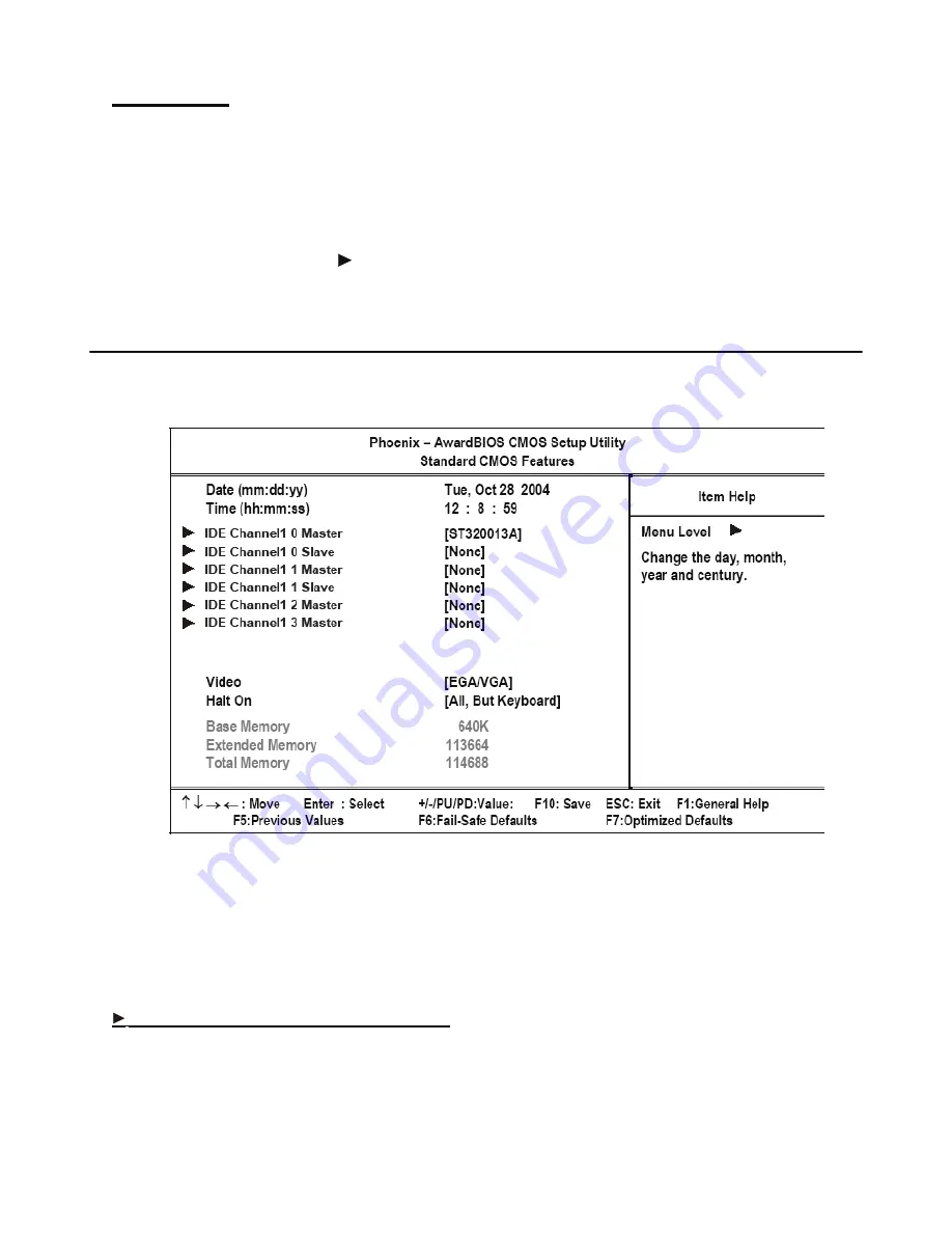
Selecting Standard CMOS Features on the main menu displays the following menu:
Figure 2.2
Standard CMOS Features menu
Date and Time
The Date and Time items show the current date and time held by the PT-5700. If you are running a Windows OS, these
items are automatically updated whenever you make changes to the Windows Date and Time Properties utility.
IDE Primary/Secondary Master/Slave
This field is used to configure the IDE hard drive installed in the system. Move the cursor to highlight the IDE Pri-
mary/Secondary Master/Slave fields and press <Enter>. The IDE Primary Master submenu opens:
Содержание PT-5700
Страница 1: ...PT 5700 Service Manual...
Страница 2: ......
Страница 8: ...vi...
Страница 14: ...6 Getting Started...
Страница 42: ...34 BIOS Setup Utility...
Страница 45: ...Chipset driver 37 5 Click Next to continue 6 Select Yes I want to restart my computer now and then click Finish...
Страница 48: ...40 Installing Drivers and Software 5 Click Next to continue 6 Click Next to continue...
Страница 50: ...42 Installing Drivers and Software 4 Click Install to continue 5 Click Finish...
Страница 53: ...Touch screen driver 45 8 Click Next to continue 9 Click Next to continue...
Страница 62: ...54 Locating the Problem...
Страница 71: ...Replacing Parts 63 5 Disconnect the 2 cables 6 Remove the 3 screws M3 x 4 mm silver 7 Remove the MSR...
Страница 76: ...68 Replacing Field Replaceable Units FRUs 5 Remove the 4 screws M3 x 4 mm silver 6 Remove the mainboard...
Страница 80: ...72 Replacing Field Replaceable Units FRUs 4 Remove the waterproof seal...
Страница 86: ...78 Appendix Exploded Diagrams and Parts List Display Parts and Cables Figure 6 2 Exploded diagram cables...
Страница 88: ...80 Appendix Exploded Diagrams and Parts List...