P300H
P300 Series Modem Installation and Operating Handbook
Page 214
Operating over satellite
without
TS ID maintenance is comparable to using an external Drop/Insert mux
interfaced in our 2 x 64kbps example to the modem at 128kbps. Once demultiplexed to 128kbps the
start and end boundaries of each timeslot are lost in the continuous 128kbps data stream. Without the
TS ID maintenance there would be 16 different ways (2 x 8 bits per TS) that the two data streams could
be inserted back into the terrestrial PCM bearer timeslots at the receive end. One correct way, one with
channels reversed (8 bits shifted), and 14 ways (shifts of 1-7, 8-15 bits) in which parts of each channel
appeared in the channel.
Without TS ID maintenance then, Drop/Insert can only useful if all the
data dropped / inserted comprises one single data stream of N x 64kbps from a single source.
Note: Typically D/I is tested with a PRBS from a Firebird in all relevant timeslots, this is a guaranteed
way to
NOT TEST
TS ID Maintenance, as it is not required for such a test (because all the data
comprises one single data stream from a single source, the PRBS generator). Instead to verify TS ID
maintenance insert the PRBS into any
subset
of the dropped timeslots (eg just one). If the Timeslot ID is
not maintained
, you are likely to get something else back in the equivalent receive timeslot instead of
the PRBS (probably the idle code from one of the other dropped timeslots). If the Timeslot ID
is
maintained
, you should
consistently
get the PRBS back in this
same
subset or single timeslot. Bear in
mind that without TS ID maintenance, when dropping N timeslots, statistically it will still work one time in
8xN, when the random timeslot alignment happens to be correct!
The requirement is to provide:
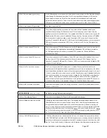
The data from each timeslot appears as a set of 8 bits from each terrestrial frame.
Timeslot boundary
maintenance
is provided by placing the data into the IBS frame, timeslot aligned after TS0. When TS0 is
located, the next 8 bits represent 8 bits from one terrestrial timeslot, the following 8 from the next etc.
1 Frame (ie 60 available data timeslots): N =
1, 2, 3, 4, 5, 6, 10, 12, 15, 20, 30
Implementation of Timeslot ID Maintenance
1) Timeslot boundary maintenance (start/end of each timeslots 8 bits) within the data stream.
2) Timeslot identity (ID) maintenance, ie which 8 bits relate to which timeslot (first, second, third etc)
within the data stream.
Timeslot Identity Maintenance
again relies on relative position to TS0. Data from the first timeslot of the
group of timeslots is always placed in the first timeslot after TS0, the second of the group in the second
TS, and so forth. Once the 8 bits of data from every timeslot have been placed in the frame, the process
repeats until the frame is full. For the
following
frame to be similarly formatted the timeslot data must fit
into the 60 available data timeslots of the satellite frame exactly (so that the next data is from the first TS
again). This brings in a complication.....
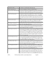
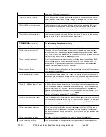
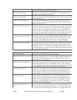
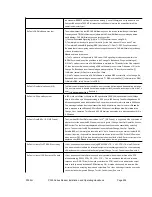
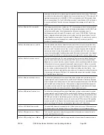
Each IBS frame has 60 timeslots available for data, and so in order to provide timeslot ID maintenance,
the number of timeslots `N` must fit into 60. This limits the values of N to:
This is less than ideal, and so a few further values are accommodated by mapping them into two frames:
2 Frames (ie 120 available data timeslots): N =
8, 24
Finally, to support one further rate, four frame are used:
4 Frames (ie 240 available data timeslots): N =
16
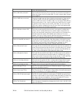
The remaining values of N cannot have Timeslot ID Maintained by groups of 1, 2, or 4 frames, these are
collectively know as the `Odd values of N`:
`Odd values of N`: N =
7, 9, 11, 13, 14, 17, 18, 19, 21, 22, 23, 25, 26, 27, 28, 29, 31
Most previous equipment could not provide timeslot ID maintenance for these `odd values of N`,
however the P300 when equipped with the Extended D/I feature uses a derivative of the IBS CAS
Multiframe (see later section "CAS Multiframe") to provide timeslot ID maintenance for even these
remaining values of N.
Содержание P300 Series
Страница 21: ...P300H P300 Series Modem Installation and Operating Handbook Page 21 F BLOCK DIAGRAM ...
Страница 22: ...P300H P300 Series Modem Installation and Operating Handbook Page 22 ...
Страница 163: ...P300H P300 Series Modem Installation and Operating Handbook Page 163 8 12 4 Eb No Explanatory Diagram ...

