


6-17
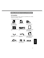
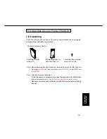
Unpacking/
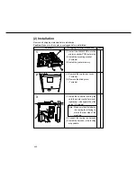
Installation
Location
Shipping material/Procedure
Check
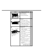
8
(1) Open the front door.
(2) Remove the control panel mount-
ing screws. (2 screws)
(3) Remove the blind cover and
screw.
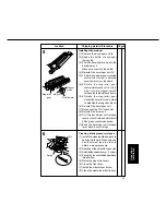
9
(1) Connect the control panel (C)
PCB harness to the control panel
(C) PCB.
(2) Connect the control panel (D)
PCB harness to the control panel
(C) PCB.
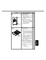
10
(1) Place the insulation sheet 1 onto
the control panel.
(2) Remove the ferrite core.
(3) Place the insulation sheet 2 onto
the control panel (C) PCB and
install them to the control panel
(4 screws).
(4) Connect the control panel (D)
PCB harness to the control panel
(B) PCB.
(5) Re-install the ferrite core.
3
1
2
Содержание FP-D350
Страница 198: ...4 77 PCB Connector and Signal Information 2 Control Panel PCB A FP D250 D350 Series CN354 CN355 Not used ...
Страница 332: ...4 211 PCB Connector and Signal Information 2 Control Panel PCB A FP D450 D600 Series CN354 CN355 Not used ...
Страница 517: ...5 79 Troubleshooting Code Item Function Factory setting US38 User information list 0 Stop 0 1 Start ...


