3-128
Chapter 3 Troubleshooting
3. Select from the fault code displayed or [Home Page]. (The "Home Page" indicates the table
of contents.)
4. The PSW displays the page of the Electronic Manual (corresponding fault of the FIP)
corresponding to the specified fault code. Or, the top page of the table of contents will be
displayed.
5. When diagnostic for the fault is completed, select either [Return to DIAG] or [Close] on the
Electronic Manual.
6. The display returns to the Electronic Manual Connection Information screen.
7. If you select [Cancel], the display will return to the same Service Mode screen as appeared
when the Electronic Manual Connection Information screen was shown for the first time.
3. 4. 2. 1. 3 The history menu linked with the Diag/Electronic Manual
Procedure
1. Select [Electronic Manual Connection History] from the system menu (which is opened by
clicking the menu box at the upper left of the screen). Or, select [History] in the Electronic
Manual Connection Information.
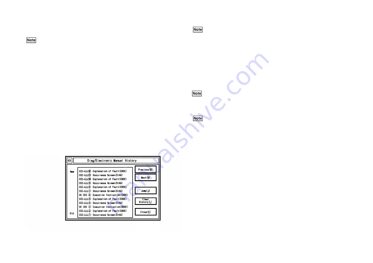
2. The Diag/Electronic Manual History screen is displayed. (Fig. 1)
(Fig. 1) j0mf2405
3. Select the screen you want to display from the history column, and select [Jump].
4. The PSW displays the specified Diag (Service Mode) screen or the Electronic Manual
screen.
5. Select [Return to Diag] or [Close] on the Electronic Manual.
6. The previous Diag (Service Mode) screen before the Diag/Electronic Manual History
screen will be displayed. (E.g.: For the electronic manual transferred from the description
(EDOC) of the CCC-LLL2 Fault in Figure 1, the system will return to the Diag (Service
Mode) screen for the CCC-LLL2 Occurrence screen (DIAG).
7. When you select [Close] on the Diag (Service Mode) screen, the PSW returns to the Electronic
Manual screen immediately shown before the Diag/Electronic Manual History screen.
8. Select [Clear History] on the Diag/Electronic Manual History screen.
9. Clear the Diag/Electronic Manual History to display the first Diag (Service Mode) screen of
the history. (E.g.: For the electronic manual transferred from the description (EDOC) of the
CCC-LLL1 Fault in Figure 1, the system will return to the Diag (Service Mode) screen for
the CCC-LLL2 Occurrence screen (DIAG).
• There are primary (main cause) faults and secondly faults. The machine identifies
those fault types. Only when the machine add identifiers to them, the identifiers
(Example:<p>) will be added and displayed. This purpose is to clarify the
cause-effect relationship between primary and secondry faults.
• For [History], refer to 3.4.2.1.3 The history menu linked with the Diag/Electronic
Manual.
The PSW has all the progress history of the Diag/EDOC (Electronic Manual). The
contents of the history display is added on the messages below:
a. DIAG -> The key information when linking DIAG -> Electronic Manual (Fault Code)
b. The key information when linking Electronic Manual - DIAG (DC NO.)
The following messages are added to the displays above.
a-1 "Occurrence Screen (DIAG)"
a-2 "Explanation of Fault (EDOC)"
b-1 "Execution Instructions (EDOC)"
The indications such as CCC-LLL(1) of Fig. 1 are descriptions for convenience, and the
PSW actually displays the Chain Link No. that represents the Fault Code.
This [Jump] also becomes a target of the Diag/Electronic Manual link history.
• In case the progress destination is the Diag screen, you can link the Diag operation,
execution and the Electronic Manual.
• If transfer destination is an Electronic manual, linking with Diag is possible. In this
case, the appropriate Diag (Service Mode) will be linked and displayed by the
execution instruction operation such as double-clicking on the description portion
of DCXXX[CCC-LLL] in FIP.
• In case the PSW linked the Diag to the Electronic Manual here, they will be a target
of linkage history.
• In case the PSW cannot link the specified Diag, it displays " [!] The items or
functions specified by the machine in connection cannot be executed now." on the
message screen.
Содержание DP-C321
Страница 4: ...This page is intentionally left blank ...
Страница 5: ...Chapter 1 General ...
Страница 22: ...1 16 Chapter 1 General 1 3 Type of Paper ...
Страница 23: ...1 17 Chapter 1 General ...
Страница 24: ...Chapter 2 Maintenance ...
Страница 63: ...Chapter 3 Troubleshooting ...
Страница 118: ...3 44 Chapter 3 Troubleshooting I F PWB PL9 1 MCU PWB PL13 1 ...
Страница 378: ...3 304 Chapter 3 Troubleshooting Read Write Read Write Description Memory Spool 512 KB 32 MB 256 KB interval ...
Страница 445: ...Chapter 4 Parts List ...
Страница 527: ...4 80 Chapter 4 Parts List 17 RACK PL17 1 Rack Ref No Part No Description 7901 17E9471X Rack Caster Front j0mf51901 ...
Страница 548: ......


