28
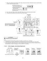
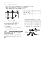
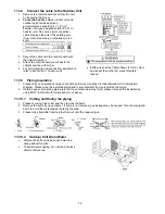
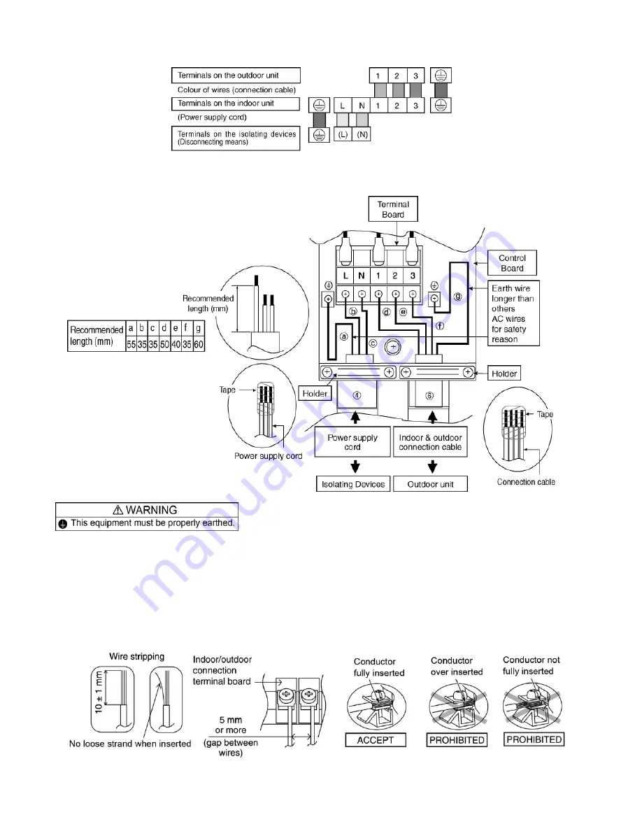
7 Remove the tapes and connect the power supply cord and connection cable between indoor unit and outdoor
unit according to the diagram below.
8 Secure the power supply cord and connection cable onto the control board with the holder.
9 Close grille door by tighten with screw and close the front panel.
Note:
•
Isolating Devices (Disconnecting means) should have minimum 3.0 mm contact gap.
•
Ensure the colour of wires of outdoor unit and the terminal Nos. are the same to the indoor’s respectively.
•
Earth wire shall be Yellow/Green (Y/G) in colour and longer than other AC wires as shown in the figure for the
electrical safety in case of the slipping out of the cord from the anchorage.
11.2.4.1 Wire
Stripping,
Connecting Requirement
Содержание CS-AE9NKE
Страница 12: ...12 4 Location of Controls and Components 4 1 Indoor Unit 4 2 Outdoor Unit 4 3 Remote Control ...
Страница 13: ...13 5 Dimensions 5 1 Indoor Unit ...
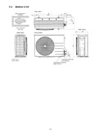
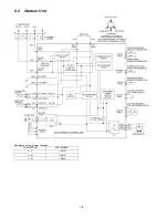
Страница 14: ...14 5 2 Outdoor Unit ...
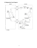
Страница 15: ...15 6 Refrigeration Cycle Diagram ...
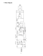
Страница 16: ...16 7 Block Diagram ...
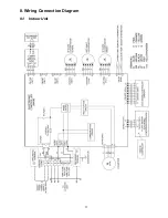
Страница 17: ...17 8 Wiring Connection Diagram 8 1 Indoor Unit ...
Страница 18: ...18 8 2 Outdoor Unit Resistance of Compressor Windings CONNECTION 5RD132XBE21 U V 1 897Ω U W 1 907Ω V W 1 882Ω ...
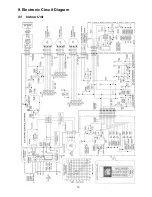
Страница 19: ...19 9 Electronic Circuit Diagram 9 1 Indoor Unit ...
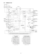
Страница 20: ...20 9 2 Outdoor Unit ...
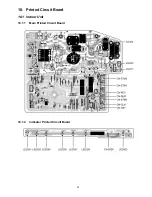
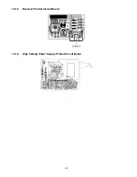
Страница 22: ...22 10 1 3 Receiver Printed Circuit Board 10 1 4 High Voltage Power Supply Printed Circuit Board ...
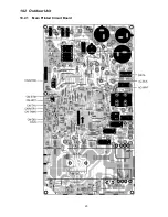
Страница 23: ...23 10 2 Outdoor Unit 10 2 1 Main Printed Circuit Board ...
Страница 29: ...29 ...
Страница 91: ...91 Figure 3 Figure 4 16 1 1 3 To remove discharge grille Figure 5 ...
Страница 92: ...92 16 1 1 4 To remove control board Figure 6 16 1 1 5 To remove cross flow fan and indoor fan motor Figure 7 ...
Страница 93: ...93 Figure 8 Figure 9 ...
Страница 94: ...94 Figure 10 ...

