51
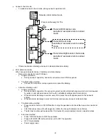
13.2.6 Dew Prevention Control 2
•
To prevent dew formation at indoor unit discharge area.
•
This control starts if all conditions continue for 20 minutes:
o
Operated with Cooling or Soft Dry Mode.
o
Indoor intake temperature is between 25°C and 29°C.
o
Outdoor air temperature is less than 30°C.
o
Quiet Lo fan speed.
•
This control stopped if:
o
When receive air swing change signal from Remote Control.
•
The horizontal airflow angle will be fixed at facing front.
•
The vertical airflow angle will be fixed at 25° (Upper vane) 7° (Lower vane).
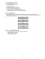
13.2.7 Odor
Cut
Control
•
To reduce the odor released from the unit.
o
Start
Condition
AUTO FAN Speed is selected during COOL or DRY operation.
During freeze prevention control and timer preliminary operation, this control is not applicable.
o
Control
content
Depends on compressor conditions:
•
Compressor
OFF
→
Compressor ON.
The indoor unit fan stops temporarily and then starts to blow at minimum airflow for 30 seconds.
•
Compressor
ON
→
Compressor OFF.
The indoor unit fan stops for 90 seconds and then blows at minimum airflow for 20 seconds.
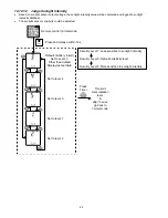
13.3 Protection Control For Heating Operation
13.3.1 Intake Air Temperature Control
Compressor will operate at limited freq., if indoor intake air temperature is 30°C or above.
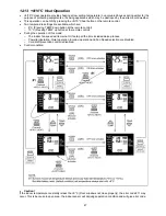
13.3.2 Outdoor Air Temperature Control
•
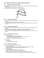
The Max current value is regulated when the outdoor air temperature rise above 14°C in order to avoid
compressor overloading.
14°C
12°C
Outdoor air temperature
Current Regulated
Free Within Max Limit
Содержание CS-AE9NKE
Страница 12: ...12 4 Location of Controls and Components 4 1 Indoor Unit 4 2 Outdoor Unit 4 3 Remote Control ...
Страница 13: ...13 5 Dimensions 5 1 Indoor Unit ...
Страница 14: ...14 5 2 Outdoor Unit ...
Страница 15: ...15 6 Refrigeration Cycle Diagram ...
Страница 16: ...16 7 Block Diagram ...
Страница 17: ...17 8 Wiring Connection Diagram 8 1 Indoor Unit ...
Страница 18: ...18 8 2 Outdoor Unit Resistance of Compressor Windings CONNECTION 5RD132XBE21 U V 1 897Ω U W 1 907Ω V W 1 882Ω ...
Страница 19: ...19 9 Electronic Circuit Diagram 9 1 Indoor Unit ...
Страница 20: ...20 9 2 Outdoor Unit ...
Страница 22: ...22 10 1 3 Receiver Printed Circuit Board 10 1 4 High Voltage Power Supply Printed Circuit Board ...
Страница 23: ...23 10 2 Outdoor Unit 10 2 1 Main Printed Circuit Board ...
Страница 29: ...29 ...
Страница 91: ...91 Figure 3 Figure 4 16 1 1 3 To remove discharge grille Figure 5 ...
Страница 92: ...92 16 1 1 4 To remove control board Figure 6 16 1 1 5 To remove cross flow fan and indoor fan motor Figure 7 ...
Страница 93: ...93 Figure 8 Figure 9 ...
Страница 94: ...94 Figure 10 ...

