105
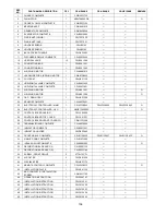
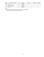
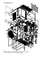
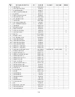
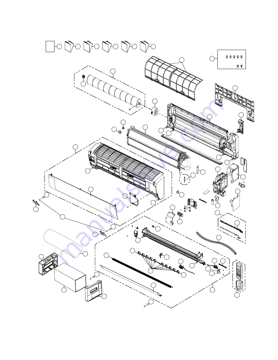
18. Exploded View and Replacement Parts List
18.1 Indoor Unit
50
52
53
51
40
41
28
34
31
38
4
30
36
26
2
39
3
33
29
27
35
1
6
42
10
43
25
32
O/I
44
I/I
45
I/I
46
I/I
47
I/I
48
I/I
49
23
B
B
B
11
19
18
14
21
22
37
20
15
12
5
16
17
A
A
B
A
A
A
B
B
A
CWH55025J
CWH55051J
9
8
7
24
9a
Note
The above exploded view is for the purpose of parts disassembly and replacement.
The non-numbered parts are not kept as standard service parts.
Содержание CS-AE9NKE
Страница 12: ...12 4 Location of Controls and Components 4 1 Indoor Unit 4 2 Outdoor Unit 4 3 Remote Control ...
Страница 13: ...13 5 Dimensions 5 1 Indoor Unit ...
Страница 14: ...14 5 2 Outdoor Unit ...
Страница 15: ...15 6 Refrigeration Cycle Diagram ...
Страница 16: ...16 7 Block Diagram ...
Страница 17: ...17 8 Wiring Connection Diagram 8 1 Indoor Unit ...
Страница 18: ...18 8 2 Outdoor Unit Resistance of Compressor Windings CONNECTION 5RD132XBE21 U V 1 897Ω U W 1 907Ω V W 1 882Ω ...
Страница 19: ...19 9 Electronic Circuit Diagram 9 1 Indoor Unit ...
Страница 20: ...20 9 2 Outdoor Unit ...
Страница 22: ...22 10 1 3 Receiver Printed Circuit Board 10 1 4 High Voltage Power Supply Printed Circuit Board ...
Страница 23: ...23 10 2 Outdoor Unit 10 2 1 Main Printed Circuit Board ...
Страница 29: ...29 ...
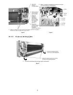
Страница 91: ...91 Figure 3 Figure 4 16 1 1 3 To remove discharge grille Figure 5 ...
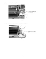
Страница 92: ...92 16 1 1 4 To remove control board Figure 6 16 1 1 5 To remove cross flow fan and indoor fan motor Figure 7 ...
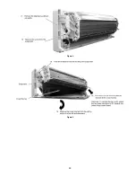
Страница 93: ...93 Figure 8 Figure 9 ...
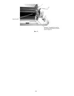
Страница 94: ...94 Figure 10 ...

