2
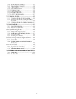
12.6
Quiet operation (Heating) ...........................37
12.7
Powerful Mode Operation...........................38
12.8
Timer Control..............................................38
12.9
Auto Restart Control...................................38
12.10
Indication Panel ..........................................39
12.11
nanoe-G Operation.....................................40
12.12
ECONAVI Operation ..................................43
12.13
+8/10°C Heat Operation.............................47
13.
Protection Control............................................48
13.1
Protection Control For All Operations.........48
13.2
Protection Control For Cooling & Soft Dry
Operation....................................................50
13.3
Protection Control For Heating Operation..51
14.
Servicing Mode .................................................53
14.1
Auto OFF/ON Button ..................................53
14.2
Remote Control Button...............................54
15.
Troubleshooting Guide....................................55
15.1
Refrigeration Cycle System........................55
15.2
Breakdown Self Diagnosis Function...........57
15.3
Error Code Table ........................................58
15.4
Self-diagnosis Method................................60
16.
Disassembly and Assembly Instructions ......90
16.1
Indoor Unit ..................................................90
16.2
Outdoor Electronic Controller Removal
Procedure ...................................................95
17.
Technical Data ..................................................96
17.1
Operation Characteristics...........................96
17.2
Sensible Capacity Chart.......................... 104
18.
Exploded View and Replacement Parts List105
18.1
Indoor Unit ............................................... 105
18.2
Outdoor Unit ............................................ 108
Содержание CS-AE9NKE
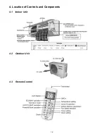
Страница 12: ...12 4 Location of Controls and Components 4 1 Indoor Unit 4 2 Outdoor Unit 4 3 Remote Control ...
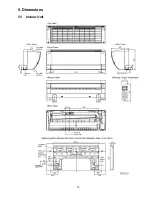
Страница 13: ...13 5 Dimensions 5 1 Indoor Unit ...
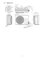
Страница 14: ...14 5 2 Outdoor Unit ...
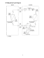
Страница 15: ...15 6 Refrigeration Cycle Diagram ...
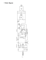
Страница 16: ...16 7 Block Diagram ...
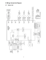
Страница 17: ...17 8 Wiring Connection Diagram 8 1 Indoor Unit ...
Страница 18: ...18 8 2 Outdoor Unit Resistance of Compressor Windings CONNECTION 5RD132XBE21 U V 1 897Ω U W 1 907Ω V W 1 882Ω ...
Страница 19: ...19 9 Electronic Circuit Diagram 9 1 Indoor Unit ...
Страница 20: ...20 9 2 Outdoor Unit ...
Страница 22: ...22 10 1 3 Receiver Printed Circuit Board 10 1 4 High Voltage Power Supply Printed Circuit Board ...
Страница 23: ...23 10 2 Outdoor Unit 10 2 1 Main Printed Circuit Board ...
Страница 29: ...29 ...
Страница 91: ...91 Figure 3 Figure 4 16 1 1 3 To remove discharge grille Figure 5 ...
Страница 92: ...92 16 1 1 4 To remove control board Figure 6 16 1 1 5 To remove cross flow fan and indoor fan motor Figure 7 ...
Страница 93: ...93 Figure 8 Figure 9 ...
Страница 94: ...94 Figure 10 ...


