8
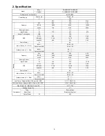
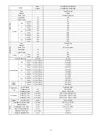
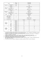
Indoor CS-HE12NKE
Model
Outdoor CU-HE12NKE
Performance Test Condition
EUROVENT
Phase, Hz
Single, 50
Power Supply
V 230
Min.
Mid.
Max.
kW
0.85 3.50 4.00
BTU/h 2900
11900
13600
Capacity
kcal/h 730
3010
3440
Running
Current
A
— 3.9 —
Input
Power
W
170 830 990
Annual Consumption
kWh
—
415
—
W/W
5.00 4.22 4.04
BTU/hW
17.06 14.34 13.74
EER
kcal/hW
4.29 3.63 3.47
Power Factor
%
—
93
—
dB-A
42 / 29 / 26
Indoor Noise (H / L / QLo)
Power Level dB
58 / 45 / 42
dB-A
48 / - / -
Cooling
Outdoor Noise (H / L / QLo)
Power Level dB
63 / - / -
kW
0.85 4.20 7.70
BTU/h 2900
14300
26300
Capacity
kcal/h 730
3610
6620
Running
Current
A
— 4.0 —
Input Power
W
165
845
2.26k
W/W
5.15 4.97 3.41
BTU/hW
17.58 16.92 11.64
COP
kcal/hW
4.42 4.27 2.93
Power Factor
%
—
92
—
dB-A
44 / 33 / 30
Indoor Noise (H / L / QLo)
Power Level dB
60 / 49 / 46
dB-A
50 / - / -
Heating
Outdoor Noise (H / L / QLo)
Power Level dB
65 / - / -
Low Temp. : Capacity (kW) / I.Power (W) / COP
5.58 / 2.00k / 2.79
Extr Low Temp. : Capacity (kW) / I.Power (W) / COP
4.60 / 1.90k / 2.42
Max Current (A) / Max Input Power (W)
10.6 / 2.28k
Starting Current (A)
4.0
Type
Rotary
Motor
Motor Type
Brushless (4-poles)
Compressor
Output Power
W
900
Содержание CS-AE9NKE
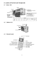
Страница 12: ...12 4 Location of Controls and Components 4 1 Indoor Unit 4 2 Outdoor Unit 4 3 Remote Control ...
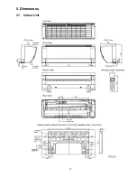
Страница 13: ...13 5 Dimensions 5 1 Indoor Unit ...
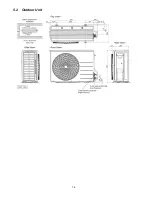
Страница 14: ...14 5 2 Outdoor Unit ...
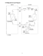
Страница 15: ...15 6 Refrigeration Cycle Diagram ...
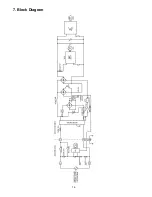
Страница 16: ...16 7 Block Diagram ...
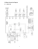
Страница 17: ...17 8 Wiring Connection Diagram 8 1 Indoor Unit ...
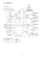
Страница 18: ...18 8 2 Outdoor Unit Resistance of Compressor Windings CONNECTION 5RD132XBE21 U V 1 897Ω U W 1 907Ω V W 1 882Ω ...
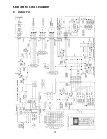
Страница 19: ...19 9 Electronic Circuit Diagram 9 1 Indoor Unit ...
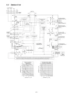
Страница 20: ...20 9 2 Outdoor Unit ...
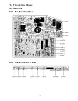
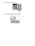
Страница 22: ...22 10 1 3 Receiver Printed Circuit Board 10 1 4 High Voltage Power Supply Printed Circuit Board ...
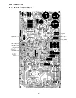
Страница 23: ...23 10 2 Outdoor Unit 10 2 1 Main Printed Circuit Board ...
Страница 29: ...29 ...
Страница 91: ...91 Figure 3 Figure 4 16 1 1 3 To remove discharge grille Figure 5 ...
Страница 92: ...92 16 1 1 4 To remove control board Figure 6 16 1 1 5 To remove cross flow fan and indoor fan motor Figure 7 ...
Страница 93: ...93 Figure 8 Figure 9 ...
Страница 94: ...94 Figure 10 ...


