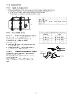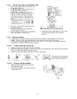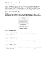
36
12.4.1 Vertical
Airflow
Upper Vane Angle (°)
Lower Vane Angle (°)
Operation Mode
Airflow Direction
1 2 3 4 5 1 2 3 4 5
A 25
17
B 55
37
Auto with Heat
Exchanger
Temperature
C 25
17
Summer House
55
37
Heating
Manual
20 45 55 65 70 17 27 37 47 56
Auto
45 ~ 70
2 ~ 39
Cooling and Fan
Manual
20 25 50 55 70 2 7 17 27 39
Auto
45 ~ 70
2 ~ 39
Soft Dry
Manual
20 25 50 55 70 2 7 17 27 39
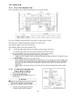
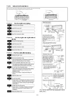
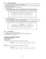
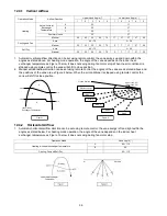
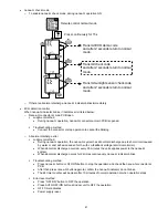
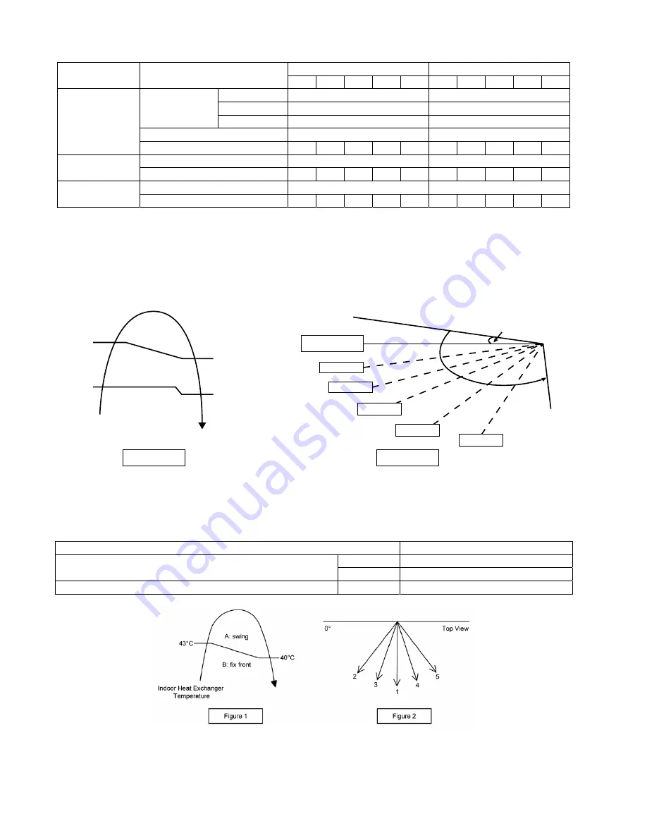
1. Automatic vertical airflow direction can be set using remote control; the vane swings up and down within the
angles as stated above. For heating mode operation, the angle of the vane depands on the indoor heat
exchanger temperature as Figure 1 below. It does not swing during fan motor stop. When the air conditioner is
stopped using remote control, the vane will shift to close position.
2. Manual vertical airflow direction can be set using remote control; the angles of the vane are as stated above and
the positions of the vane are as Figure 2 below. When the air conditioner is stopped using remote control, the
vane will shift to close position.
58°C
50°C
Indoor Heat
Exchanger Temperature
36°C
30°C
C
A
Figure 1
B
Figure 2
Upper vane: 60°
Lower vane: 58°
Reference point
Closed Position
Step 1
Step 2
Step 3
Step 4
Step 5
12.4.2 Horizontal
Airflow
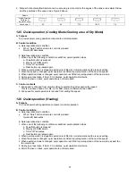
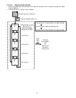
1. Automatic horizontal airflow direction can be set using remote control; the vane swings left and right within the
angles as stated below. For heating mode operation, the angle of the vane depends on the indoor heat
exchanger temperature as Figure 1 below. It does not swing during fan motor stop.
Operation Mode
Vane Angle (°)
A
65 ~ 115
Heating, with heat exchanger temperature
B 90
Cooling, Fan and Soft Dry
65 ~ 115
Содержание CS-AE9NKE
Страница 12: ...12 4 Location of Controls and Components 4 1 Indoor Unit 4 2 Outdoor Unit 4 3 Remote Control ...
Страница 13: ...13 5 Dimensions 5 1 Indoor Unit ...
Страница 14: ...14 5 2 Outdoor Unit ...
Страница 15: ...15 6 Refrigeration Cycle Diagram ...
Страница 16: ...16 7 Block Diagram ...
Страница 17: ...17 8 Wiring Connection Diagram 8 1 Indoor Unit ...
Страница 18: ...18 8 2 Outdoor Unit Resistance of Compressor Windings CONNECTION 5RD132XBE21 U V 1 897Ω U W 1 907Ω V W 1 882Ω ...
Страница 19: ...19 9 Electronic Circuit Diagram 9 1 Indoor Unit ...
Страница 20: ...20 9 2 Outdoor Unit ...
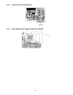
Страница 22: ...22 10 1 3 Receiver Printed Circuit Board 10 1 4 High Voltage Power Supply Printed Circuit Board ...
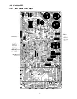
Страница 23: ...23 10 2 Outdoor Unit 10 2 1 Main Printed Circuit Board ...
Страница 29: ...29 ...
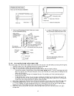
Страница 91: ...91 Figure 3 Figure 4 16 1 1 3 To remove discharge grille Figure 5 ...
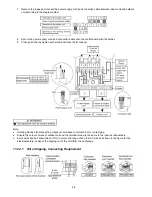
Страница 92: ...92 16 1 1 4 To remove control board Figure 6 16 1 1 5 To remove cross flow fan and indoor fan motor Figure 7 ...
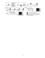
Страница 93: ...93 Figure 8 Figure 9 ...
Страница 94: ...94 Figure 10 ...

