38
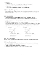
C. Control contents
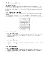
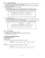
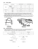
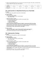
a. Fan Speed manual
1. Fan speed is changed from normal setting to quiet setting of respective fan speed.
This is to reduce sound of Hi, Me, Lo for 3dB.
2. Fan speed for quiet operation is reduced from setting fan speed.
b. Fan Speed Auto
1. Indoor FM RPM depends on pipe temp sensor of indoor heat exchanger.
12.7 Powerful Mode Operation
•
When the powerful mode is selected, the internal setting temperature will shift lower up to 2°C (for Cooling/Soft
Dry) or higher up to 3.5°C (for Heating) than remote control setting temperature for 20 minutes to achieve the
setting temperature quickly.
12.8 Timer Control
•
There are 2 sets of ON and OFF timer available to turn the unit ON or OFF at different preset time.
•
If more than one timer had been set, the upcoming timer will be displayed and will activate in sequence.
12.8.1 ON
Timer
Control
•
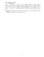
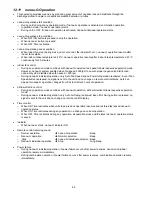
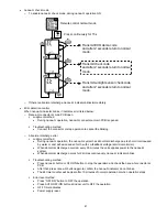
ON timer 1 and ON timer 2 can be set using remote control, the unit with timer set will start operate earlier than
the setting time.
This is to provide a comfortable environment when reaching the set ON time.
•
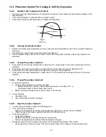
60 minutes before the set time, indoor (at fan speed of Lo-) and outdoor fan motor start operate for 30 seconds to
determine the indoor intake air temperature and outdoor air temperature in order to judge the operation starting
time.
•
From the above judgment, the decided operation will start operate earlier than the set time as shown below.
12.8.2 OFF Timer Control
OFF timer 1 and OFF timer 2 can be set using remote control, the unit with timer set will stop operate at set time.
12.9 Auto Restart Control
1. When the power supply is cut off during the operation of air conditioner, the compressor will re-operate within
three to four minutes (there are 10 patterns between 2 minutes 58 seconds and 3 minutes 52 seconds to be
selected randomly) after power supply resumes.
2. This type of control is not applicable during ON/OFF Timer setting.
3. This control can be omitted by open the circuit of JP1 at indoor unit printed circuit board.
Содержание CS-AE9NKE
Страница 12: ...12 4 Location of Controls and Components 4 1 Indoor Unit 4 2 Outdoor Unit 4 3 Remote Control ...
Страница 13: ...13 5 Dimensions 5 1 Indoor Unit ...
Страница 14: ...14 5 2 Outdoor Unit ...
Страница 15: ...15 6 Refrigeration Cycle Diagram ...
Страница 16: ...16 7 Block Diagram ...
Страница 17: ...17 8 Wiring Connection Diagram 8 1 Indoor Unit ...
Страница 18: ...18 8 2 Outdoor Unit Resistance of Compressor Windings CONNECTION 5RD132XBE21 U V 1 897Ω U W 1 907Ω V W 1 882Ω ...
Страница 19: ...19 9 Electronic Circuit Diagram 9 1 Indoor Unit ...
Страница 20: ...20 9 2 Outdoor Unit ...
Страница 22: ...22 10 1 3 Receiver Printed Circuit Board 10 1 4 High Voltage Power Supply Printed Circuit Board ...
Страница 23: ...23 10 2 Outdoor Unit 10 2 1 Main Printed Circuit Board ...
Страница 29: ...29 ...
Страница 91: ...91 Figure 3 Figure 4 16 1 1 3 To remove discharge grille Figure 5 ...
Страница 92: ...92 16 1 1 4 To remove control board Figure 6 16 1 1 5 To remove cross flow fan and indoor fan motor Figure 7 ...
Страница 93: ...93 Figure 8 Figure 9 ...
Страница 94: ...94 Figure 10 ...

