Aicure ANUP5255V2
Setting and UV irradiation by external devices
49
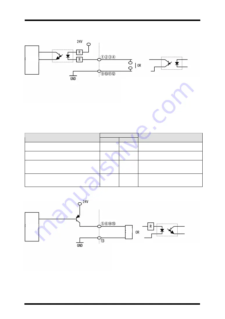
Connection diagram
■
Output signal
Machine statuses such as lamp ON and fault occurrence can be seen by output signals from the
AICURE.
Pin No.
Output signal
+
GND
Operation
Shutter OPEN confirmation (under UV
irradiation)
⑤
⑬
When the shutter opens (UV
irradiation), the output turns on.
Lamp ON confirmation
⑥
⑬
When the lamp comes on, the
output turns on.
Ready (Lamp stabilized)
⑭
⑬
When the lamp ON state
becomes stabilized, the output
turns on. (UV irradiation is ready)
Fault detection
⑮
⑬
When some fault occurs in the
AICURE body, the output turns
on.
Connection diagram
The ratings of a load to be connected to the signal
output should be as follows:
・
Voltage: 24 V maximum
・
Current: 100 mA maximum
Internal
circuit
The ratings of the ON contact or transistor
used should be as follows:
・
Withstand voltage: 30 V min.
・
Current: 100 mA maximum (24 V)
Each control signal should be used
independently.
Internal
circuit
Load


