Operating Instructions
Vol.1
ENGLISH
Before operating this product, please read the instructions carefully and save this manual
for future use.
VQT3S21
SS0711TO0 -PS
Printed in japan
Volume
Note that Operation Instructions Vol.1 describes basic operations
of the Memory Card Portable Recorder.
For instructions on advanced operations of the Memory Card
Portable Recorder, refer to Operating Instructions Vol. 2 (pdf file)
contained in the supplied CD-ROM.
1
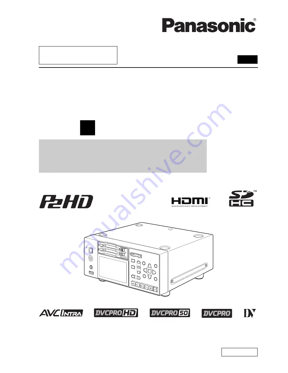
Memory Card Portable Recorder
Model No.
AG-HPD24P
Model No.
AG-HPD24E
■
This product is eligible for the P2HD 5 Year
Warranty Repair Program. For details,
see page 90 of Vol.2.