15
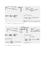
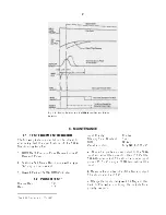
Fig. 4.9. System for Detector Current and Voltage
Measurements.
Fig. 4.10. Silicon Detector Back Current vs Bias Voltage.
CURRENT-VOLTAGEMEASUREMENTSFORSi
and Ge DETECTORS
The amplifier system is not
directlyinvolvedinsemiconductordetectorcurrent-
voltage measurements, but the amplifier serves to
permit noise monitoring during the setup. The
detector noise measurement is a more sensitive
methodthanacurrentmeasurementofdetermining
the maximum detector voltage that should be used
because the noise increases more rapidly than the
reverse current at the onset of detectorbreakdown.
Make this measurement in the absence of a
source.
Figure 4.9 shows the setup required for current-
voltage measurements. An ORTEC 428 Bias
Supply is used as the voltage source. Bias voltage
should be applied slowly and reduced when noise
increases rapidly as a function of applied bias.
Figure 4.10 shows several typical current-voltage
curvesforORTECsiliconsurface-barrierdetectors.
When it is possible to float the microammeter at the
detector bias voltage, the method of detector
current measurement shown by the dashed lines in
Fig. 4.9 is preferable. The detector is grounded as
in normal operation and the microammeter is
connectedtothecurrentmonitoring jack on the 428
Detector Bias Supply.
4.9. OPERATION IN SPECTROSCOPY
SYSTEMS
HIGH-RESOLUTION ALPHA-PARTICLE
SPECTROSCOPYSYSTEM
Theblock diagramof
a high-resolution Spectroscopy system for
measuring natural alpha particle radiation is shown
in Fig. 4.11. Alpha-particle resolution is obtained in
the following manner:
a.
Use appropriate amplifier gain. Accumulate the
alpha peak in the MCA.
b.
Slowly increase the amplifier gain until the alpha
peak is spread over 5 to 10 channels.
c.
Calibrate the analyzer in keV per channel using
the pulser and the known energy of the alpha peak
(see "Calibration of Test Pulser") or two known
energy alpha peaks.
d.
Calculate the resolution by measuring the
number of channels at the FWHM level in the peak
and converting this to keV.
HIGH-RESOLUTION GAMMA SPECTROSCOPY
SYSTEM
A high-resolution gamma spectroscopy
system block diagram is shown in Fig. 4.12. When
germanium detectors that are cooled by a liquid
nitrogen cryostat are used, it is possible to obtain
resolutionsfromabout1keVFWHMup(depending
on the energy of the incident radiation and the size
and quality of the detector). Reasonable care is
required to obtain such results. So me guidelines
for obtaining optimum resolution are:
a.
Keep interconnection capacities between the
detector and preamplitier to an absolute minimum
(no long cables).
b.
Keephumiditylownearthedetector-preamplifier
junction.
c.
Operate the amplifier with the shaping time that
provides the best signal-to-noise ratio.
d
. Operate at the highestallowabledetectorbias to
keep the input capacity low.
Содержание 572A
Страница 6: ...vi...
Страница 24: ...18 Fig 4 16 Gamma Ray Charged Particle Coincidence Experiment Fig 4 17 Gamma Ray Pair Spectrometry...
Страница 26: ...20 Fig 5 1 Amplifier Block Diagram...

