11
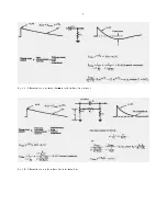
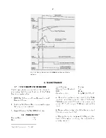
Fig. 4.2. Typical Waveforms Illustrating Pole-Zero
Adjustment Effects; Oscilloscope Trigger, 572A Busy
Output;
60
Co Source with 1.33-MeV Peak Adjusted
----
9 V;
Count Rate, 3 kHz; Shaping Time Constant, 2 µs.
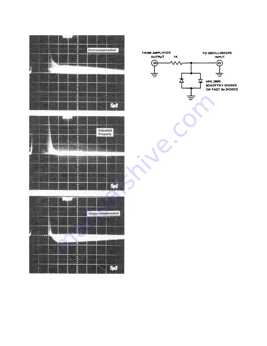
Fig. 4.3. A Clamp Circuit that Can Be Used to Prevent
Overloading the Oscilloscope Input.
that it generates output signals of alternate
polarities on the leading and trailing edges of the
square wave input signal, and these can be
compared as shown in Fig. 4.4 to achieve excellent
pole-zero cancellation.
Use the following procedure:
a.
Remove all radioactive sources from the vicinity
of the detector. Set up the system as for normal
operation, including detector bias.
b.
Set the 572A controls as for normal operation;
this includes gain, shaping, and input polarity.
c.
Connect the source of 1-kHz square waves
through an attenuator to the Test input of the
preamplifier. Adjust the attenuator so that the 572A
output amplitude is about 9 V.
d.
Observe the unipolar output of the 572A with an
oscilloscope, triggered from the 572A Busy output.
Adjust the PZ Adj control for proper response
according to Fig. 4.4. Use the clamp circuit of
Fig. 4.3 to prevent overloading the oscilloscope
input.
Figure 4.4A shows the amplifier output as a series
ofalternatepositiveandnegativeGaussianpulses.
In the other three pictures of this figure the
oscilloscope was triggered to show both positive
andnegativepulsessimultaneously.Thesepictures
show more detail to aid in proper adjustment.
4.7. BLR THRESHOLD ADJUSTMENT
After the amplifier gain and shaping have been
selected and the PZ Adj control has been set to
operateproperly for the particular shaping time, the
BLR Thresh control can be used to establish the
correct discriminator threshold for the baseline
restorer circuit. Normally, the toggle switch can be
set at Auto and the threshold level will be set
automatically just above the noise level. If desired,
Содержание 572A
Страница 6: ...vi...
Страница 24: ...18 Fig 4 16 Gamma Ray Charged Particle Coincidence Experiment Fig 4 17 Gamma Ray Pair Spectrometry...
Страница 26: ...20 Fig 5 1 Amplifier Block Diagram...

