21
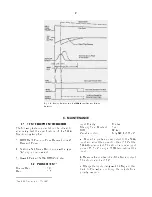
Fig. 5.2. Timing Relations in the 572A Amplifier and Pile-Up
Rejector.
6. MAINTENANCE
6.1. TEST EQUIPMENT REQUIRED
The following test equipment should be utilized to
adequately test the specifications of the 572A
Spectroscopy Amplifier:
1. ORTEC 419 Precision Pulse Generator or 448
Research Pulser.
2. Tektronix 547 Series Oscilloscope with a type
1A1 plug-in or equivalent.
3. Hewlett-Packard 3400A RMS Voltmeter.
6.2. PULSER TEST
1
Coarse Gain
1K
Gain
1.5
Input Polarity
Positive
Shaping Time Constant
1 µs
BLR
PZ Adj
Variable control
Fully CWfor 300 mV
a
. Connect a positive pulser output to the 572A
input and adjust the pulser to 10 V at the
572A Unipolar output. This should require an input
pulse of 6.6 mV, using a 100Ω terminator at the
input.
b.
Measure the positive lobe of the Bipolar output.
This should also be +10 V.
c.
Change the Input polarity switch to Neg and then
back to Pos while monitoring the outputs for a
polarity inversion.
1
See IEEE Standards, No. 301-1976.
Содержание 572A
Страница 6: ...vi...
Страница 24: ...18 Fig 4 16 Gamma Ray Charged Particle Coincidence Experiment Fig 4 17 Gamma Ray Pair Spectrometry...
Страница 26: ...20 Fig 5 1 Amplifier Block Diagram...


