11
Framing
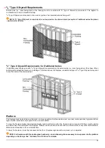
Fireplace chase may be framed with either combustible (typically wood studs) or non-combustible framing (typically metal studs).
Any framing within 18 inches from the top of the fireplace glass (viewing area) must be non-combustible.
The framing of the fireplace chase must be designed to carry the entire weight of the wall and finish material. Surrounding material
must not transfer weight to the fireplace or be connected in any way to the fireplace, with the exception of
5
/
8
” Type X drywall (or its
equivalent). It may be fastened to the front face of the fireplace with 1-inch self-tapping drywall screws 16 inches on center, with a
minimum of 2
1
/
2
inches from the metal lip (above the viewing area).
IMPORTANT: No material is permitted to extend past the
1
/
2
” metal lip surrounding the fireplace viewing area. This area
must be unobstructed to allow the heat barrier and inside glass panel to be removable.
IMPORTANT: To ensure the glass is removable after installation, Magnetic Screw (Part #M03) under the fireplace lip
must be secured tightly to the firebox and screwed in as far as possible prior to installation of framing and finish material.
If the magnet is not completely screwed down into the firebox, the lip will sit ajar to the firebox, preventing glass removal.
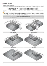
Framing Dimensions
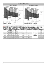
The following diagrams are for illustrative purposes only. There are multiple approved installation scenarios. A flush application is not
the only permitted application. The fireplace may be recessed into the wall. Refer to diagrams and values below and in the following
pages for details.
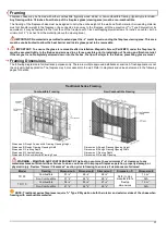
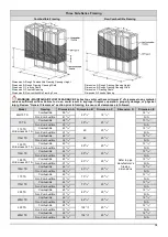
Traditional Series Framing
Combustible Framing
Non-Combustible Framing
Dimension A: Rough Combustible Framing Opening Height
Dimension B: Rough Framing Opening Width
Dimension C: Framing Depth
Dimension D: Firestop Opening
Dimension E: Non-combustible Framing Zone
Dimension A: Rough Framing Opening Height
Dimension B: Rough Framing Opening Width
Dimension C Framing Depth
Dimension D: Firestop Opening
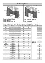
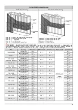
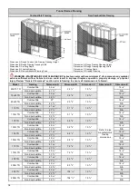
WARNING – MAINTAIN AIR FLOW CLEARANCE: Firebox top vent must have minimum 4” of clearance to any
material achieve sufficient airflow. Failure to do so could result in improper fireplace operation, property damage, or
physical injury. Review “General Clearances” section prior to framing to ensure all clearances are followed.
Model
Framing
Dimension A Dimension B Dimension C
Dimension D
Dimension E
TR 90
Combustible
51
7
/
8
”
46
1
/
8
”
26
3
/
4
”
Refer to pipe
manufacturer’s
firestop
dimensions
13
3
/
8
”
Non-Combustible
37
7
/
8
”
44
7
/
8
”
26
1
/
8
”
N/A
TR 110
Combustible
54
3
/
8
”
53
5
/
8
”
27
3
/
4
”
13
3
/
8
”
Non-Combustible
41
1
/
8
”
52
3
/
8
”
26
1
/
8
”
N/A
NOTE: Traditional series fireplaces require
5
/
8
” Type X Drywall on both the interior and exterior sides of the chase when
framing with combustible material.
Содержание Clear 130 LS
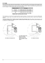
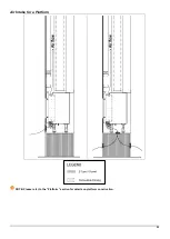
Страница 25: ...25 Air Intake for a Platform NOTE Please refer to the Platform section for details on platform construction...
Страница 53: ...53 Wiring Diagram Screen Fireplace with Interior Lighting...
Страница 54: ...54 Wiring Diagram Screen Fireplace with Interior Lighting and Ortal Power Vent...
Страница 55: ...55 Wiring Diagram Double Glass Fireplace...
Страница 56: ...56 Wiring Diagram Double Glass Fireplace with Interior Lighting...
Страница 57: ...57 Wiring Diagram Double Glass Fireplace with Interior Lighting and Ortal Power Vent...
Страница 58: ...58 Carbon Monoxide Detector Wiring Diagrams CO Kit Wiring Diagram Screen Fireplace...
Страница 59: ...59 CO Kit Wiring Diagram Double Glass Fireplace...


