5.2 PCM Conduit Installation
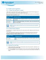
5.2.1 Pump Control/Pulser Conduit
Install conduit runs from the PV100
®
to each pump junction box. These will contain the line voltage pump
control and low voltage pulser wires with the exceptions noted below.
Wires required are per fueling point. If conduit runs to a double-sided fuel pump, then the wire requirements
listed below must be multiplied by two (x2).
Wires (per fueling
point)
Wire Requirements
Pump Control
Six (6) wires (must meet pump manufacturer’s specification for pump being
controlled)
Pulser Wire
Two- or four-wire cable shielded – 600 V-Rated – Oil & Gas resistant, Wet Loca-
tions UL-style #2567
NOTE:
Pump Pulser Wires may share Pump Control Conduit when they meet the specified
requirements.
5.2.2 Pump Pulser Conduit
As an alternative to including the pulser wiring in the pump control conduit, a separate conduit for the pulser
wire can be run.
This conduit is dedicated to bringing the pump pulser wires from the pump junction box to the terminal
pedestal. Wires required are per fueling point. If conduit runs to a double-sided fuel pump, then wire
requirements listed below must be multiplied by two (x2).
Wires (per fueling
point)
Wire Requirements
Pulser Wire
Two- or four-wires. #18 AWG 600 V-Rated – Oil & Gas resistant, Wet Loca-
tions.
NOTE:
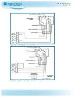
Please refer to the typical installation diagram (mechanical) for pump control conduit
wiring.
5.3 System Power Wiring
1. Pull three (3) #14-AWG wires (green [ground], black [line] and white [neutral]) from a dedicated circuit
breaker to supply power to the PV100
®
.
2. Connect power (black) and neutral (white) wires to the power connection terminal block marked “LINE”
(or “L”) and “NEUTRAL” (or “N”). Connect the green ground wire to the terminal labeled “GROUND” (or
“GND”).
Doc. No.: M1900 Rev.: 8
Page 23 of 65
Содержание M1900
Страница 48: ...Program a Carded System Doc No M1900 Rev 8 Page 48 of 65...
Страница 56: ...Appendix A PV100 Primary Board PV100 Primary Board Doc No M1900 Rev 8 Page 56 of 65...
Страница 65: ......

