


46
optics11.com
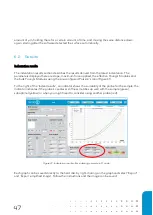
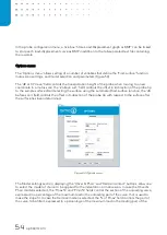
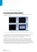
Clicking the ‘Calib’ button will guide you to the
calibration procedure, in which the Piezo stack extends
twice according to a predefined indentation profile after
performing a wavelength. During this procedure it
linearizes the interferometer signal and calculates the
‘Calibration factor’, describing the optical lever arm of
the inserted probe (see paragraph 2.4).
Clicking the ‘Indent’ button (Indent controls in software
window or ‘Enter
-
key’ on keyboard) will initiate the
movement of the Piezo stack, following the
preconfigured indentation profile.
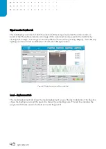
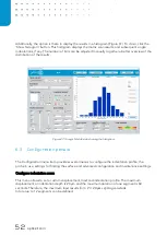
Position info
In the bottom-left, the position info is l
ocated. The ‘Position information’
section displays all current position information, as well as the absolute Z-
position of the probe (the blue bar) with respect to the (theoretical) sample
surface (Figure 39). Also the Piezo extension can be monitored and
controlled.
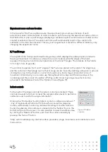
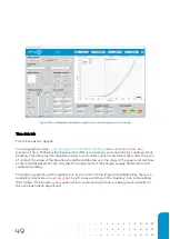
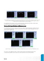
Scan controls
To the right of the ‘Position info’ section, the ‘Scan controls’ are
displayed. The ‘Scan controls’ enable the configuration of an automated
matrix of indentations across a defined
surface. The ‘#
X’ and ‘#
Y’ fields
enable definition of a number of points in X- and Y-direction to be
scanned, the ‘dX’ and ‘dY’ fields can be used to input the point
-to-point
pitch to be used, the ‘Start X’ and ‘Start Y’ fields display the starting
coor
dinates, the ‘# Scans’ field controls the
number of repetitions of the
entire scan and the ‘# Indent’ field controls the amount of indentations
per point in the matrix scan. By clicking the ‘Use XY’ button, the current
coordinates are copied into the
‘Start X’ and ‘Start Y’ fields. The ‘Start
scan’ button initiates the scanning process (Figure 40).
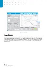
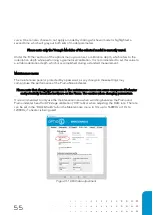
For each grid scan, a number of parameters that describe the
transportation height and the sample approach can be defined. These
controls are located in the ‘Options’ menu (Figure 19). The ‘dZ at XY
move’ field in the menu controls the point
-to-
point transportation height, and the ‘Z above surf.’
field controls the offset of the probe after finding the surface. The ‘Auto find surface’ tick
-box
controls the use of the automated find-
surface function during matrix scan. The ‘dX before scan’
field enables a step in X-
direction each time after finding the surface. The ‘Adhesion mode’ enables
the pull-off of the cantilever from the surface in case of adhesion. It does this by moving up a certain
Figure 40: Matrix scan
controls.
Figure 39: Position information.
Figure 38: Alterative keyboard stage
and piezo controls
Содержание CHIARO NANOINDENTER
Страница 1: ...PIUMA NANOINDENTER USER MANUAL ...
Страница 63: ...63 Flowchart Calibration ...
Страница 65: ......