


21
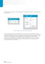
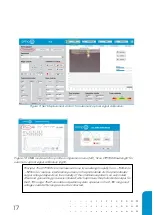
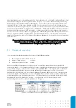
After the procedure is finished, the program will ask you whether to use the newly calculated factor
or retain the old one.
Figure 15: Message to confirm calibration value.
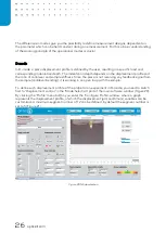
By pressing
‘U
se new
’
the software automatically saves the
new ‘Calibration
factor
’
in the probe
configuration menu. The calibration factor should be between 0.5 and 2.5. If not, repeat the optical-
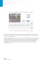
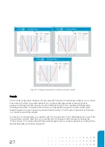
(wavelength scan) and geometrical calibration procedure. The calibration factor that is output
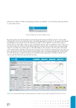
should also be checked by performing an indentation directly after the calibration. After clicking on
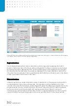
the ‘Use new factor’ button, click the ‘Displacement control’ button at the h
ome screen and press
‘Indent’ to displace the probe again on the stiff substrate. The results in the time
-data tab should
show that the piezo displacement (blue line) is equal to the cantilever bending (green line), because
the indentation starts in contact and no material deformation is expected (Figure 16). If both lines
do not superimpose, repeat the geometrical calibration by pressing the ‘Calibrate’ button and
check again the factor by viewing the time-data.
Figure 16: Load time tab showing a superimposed blue and green line, proving the used calibration factor is correct.
Содержание CHIARO NANOINDENTER
Страница 1: ...PIUMA NANOINDENTER USER MANUAL ...
Страница 63: ...63 Flowchart Calibration ...
Страница 65: ......