


13
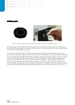
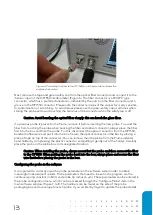
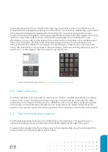
Next, remove the tape and green safety cap from the optical fiber connector and connect it to the
‘
Sensor
’ input of
the OP1550 interferometer (Figure 6). The fiber connector is a FC/APC type
connector, which has a preferred orientation, indicated by the notch on the fiber connector and a
groove in the OP1550 connector. Please note the center terminus of the connector is very sensitive
to contamination or scratching
–
to avoid issues please use the green safety cap at all times when
storing the probe and avoid touching the terminus of the connector when the safety cap is off.
Caution: Avoid bending the optical fiber sharply: this can break the glass fiber.
If a previous probe is present in the Piuma, remove it before inserting the new probe. To avoid the
fiber from touching the probe when packing the fiber and optical connector, always place the fiber
first into the box and then the probe. For this, disconnect the optical connector from the OP1550,
bundle the fiber wire and put it into the box. Secure the optical connector in the box by placing a
piece of tape on top of the connector.
You can remove then the probe from the Piuma indenter
head holder by compressing the plastic connector and pulling it gently out of the holder. Carefully
place the probe in the probe box to its designated location.
Caution: When installing the probe, always mount first the probe and then connect the fiber
to the OP1550. When putting the probe back into the box, always place and secure the fiber
wire first before placing the probe in the box.
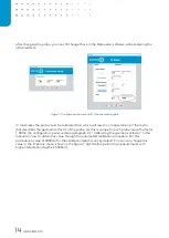
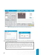
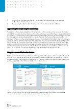
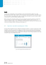
Configuring the probe in the software
It is important to correctly input the probe parameters in the software suite in order to obtain
meaningful measurement results. Probe parameters that need to be set in the program are the
cantilever spring constant (in N/m) and probe tip radius (in µm). These parameters can be entered in
the
probe configuration menu, which can be accessed through the ‘Configure Probe’ item in the
main software window (Figure 7, left). The numbers can be found on the side of the probe
packaging box and are unique for each probe. If you accidently forget to update the probe details
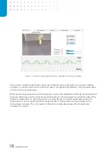
Figure 6: Connecting the fiber to the OP1550, a notch (red circle) indicates the
preferred orientation
Содержание CHIARO NANOINDENTER
Страница 1: ...PIUMA NANOINDENTER USER MANUAL ...
Страница 63: ...63 Flowchart Calibration ...
Страница 65: ......