Getting Started
12
OnRobot © 2018
www.onrobot.com
5.
Fasten the tool to the Sensor, according to the instructions from the tool
manufacturer.
The overload protection is not fully functional, if the tool is not joined
to the Sensor with an interface described in ISO 9409-1-50-4-.
2.4
Cable Connections
To connect the sensor, follow this process:
1.
Connect the 4 pin M8 cable (5m long) to the sensor. Ensure that the holes of
the cable are aligned with the pins of the connector on the sensor.
Do not rotate the cable, only rotate the connector lock.
2.
Secure the cable to the robot with cable ties.
Make sure that enough extra cable length is available around
the joints for bending.
3.
Place the Compute Box somewhere near or inside the UR robot control
cabinet and connect the 4 pin M8 sensor cable. The provided cable gland
can be used to lead the cable into the UR Control cabinet.
4.
Connect the Compute Box‘s Ethernet interface with the UR controller’s
Ethernet interface via the supplied UTP cable.
5.
Use the 3 pin M8 cable (1m long) to power the Compute Box from the UR’s
control box. Connect the brown cable to the 24V and the black cable to the
0V.
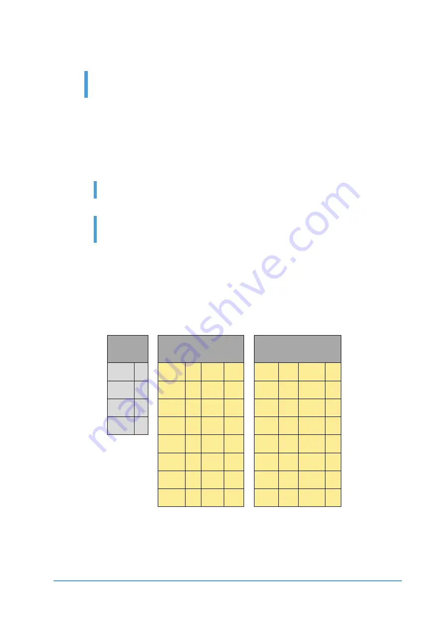
Power
Configurable Inputs
Configurable
Outputs
PWR
24V
24V
0V
OV
GND
CI0
CI4
CO0
CO4
24V
24V
24V
0V
0V
0V
CI1
CI5
CO1
CO5
24V
24V
0V
0V
CI2
CI6
CO2
CO6
24V
24V
0V
0V
CI3
CI7
CO3
CO7
For more information, refer to the UR’s documentation.
6.
Apply the correct network settings to both the Compute Box and the UR
robot. The default Compute Box IP address is 192.168.1.1, to change it, see


