90
Absolute Encoder Setup
Section 10-1
10-1 Absolute Encoder Setup
Precautions
Be sure you understand the following restrictions and take appropriate actions
as required before executing the absolute encoder setup operation.
• If a backup error or checksum error occurs in the Servo Drive, it is possi-
ble to reset the Servo Drive alarm only with a Position Control Unit with
unit version 1.2 or later. If the unit version of the Position Control Unit is
version 1.1 or earlier, it is possible to reset only the multi-turn data of the
absolute encoder. To confirm the unit version of the Position Control Unit,
refer to the IO Table Window of CX-Programmer version 4.0 or higher. For
details, refer to
Unit Versions
on page xviii.
• Commands from the ladder program will not be accepted while setting up
an absolute encoder.
Setting Up the
Absolute Encoder
1.
In the Axis Map Setting Window, select
Online - Absolute Encoder Setup
- Axis XX
(XX = 01 to 16), or right-click the axis and select
Absolute En-
coder Setup
from the pop-up menu.
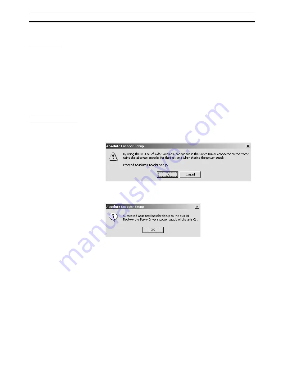
If the unit version of the connected Position Control Unit is version 1.1 or
earlier, the following dialog box will be displayed.
2.
When the absolute encoder setup has been completed, the following mes-
sage will be displayed. Cycle the Servo Drive's power supply when the fol-
lowing message is displayed.
Note
(1) If the absolute encoder setup is completed successfully, be sure to cycle
the Servo Drive's power supply.
(2) If the Absolute Encoder Setup is not completed, a message may be dis-
played to cycle the Servo Drive’s power supply, or/and restart the Position
Control Unit or cycle the PLC’s power supply. Cycle the Servo Drive’s or
PLC’s power supply, or/and restart the Position Control Unit according to
the message that is displayed.
(3) After the Absolute Encoder Setup has been completed successfully,
multi-turn data in the encoder will be reset to zero, and the previously de-
fined machine system will be changed to a different coordinate system.
Be sure to reset the zero point for the machine system. Not doing so may
result in unexpected operation.
Содержание CX-MOTION-NCF - V1.9
Страница 1: ...Cat No W436 E1 09 CX Motion NCF Ver 1 9 SYSMAC CXONE AL_C V3 CXONE AL_D V3 OPERATION MANUAL...
Страница 2: ......
Страница 3: ...CXONE AL C V3 CXONE AL D V3 CX Motion NCF Ver 1 9 Operation Manual Revised September 2009...
Страница 4: ...iv...
Страница 6: ...vi...
Страница 20: ...xx...
Страница 24: ...xxiv Application Precautions 5...
Страница 36: ...12 Connecting to PLC Section 2 2...
Страница 39: ...15 Screen Name Section 3 1 Edit Parameter Windows Edit Unit Parameters Window Edit Servo Parameters Window...
Страница 40: ...16 Screen Name Section 3 1 Monitor Windows Axis Monitor Window Unit Monitor Window...
Страница 66: ...42 Editing Servo Parameters Section 5 2...
Страница 71: ...47 Print Section 6 5 Print Samples An example of printed Unit Parameters is shown below...
Страница 92: ...68 Writing to Flash Memory Section 7 6...
Страница 98: ...74 Axis Monitor Section 8 2 2 Click the OK Button to start communications i e establish connection...
Страница 106: ...82 Axis Monitor Section 8 2...
Страница 107: ...83 SECTION 9 Test Run Operation This section describes the test run operations for each axis 9 1 Test Run 84...
Страница 112: ...88 Test Run Section 9 1...
Страница 138: ...114 Troubleshooting Section 11 3...
Страница 142: ...118 Index...
Страница 146: ...122 Revision History...


