


20
·
The displayed title is the title that was entered on the live screen the last time the
system was used.
·
If you notice any dirt, stains, or other abnormalities on the LCD monitor, see “9 Storage
and maintenance” (page 100).
TIP
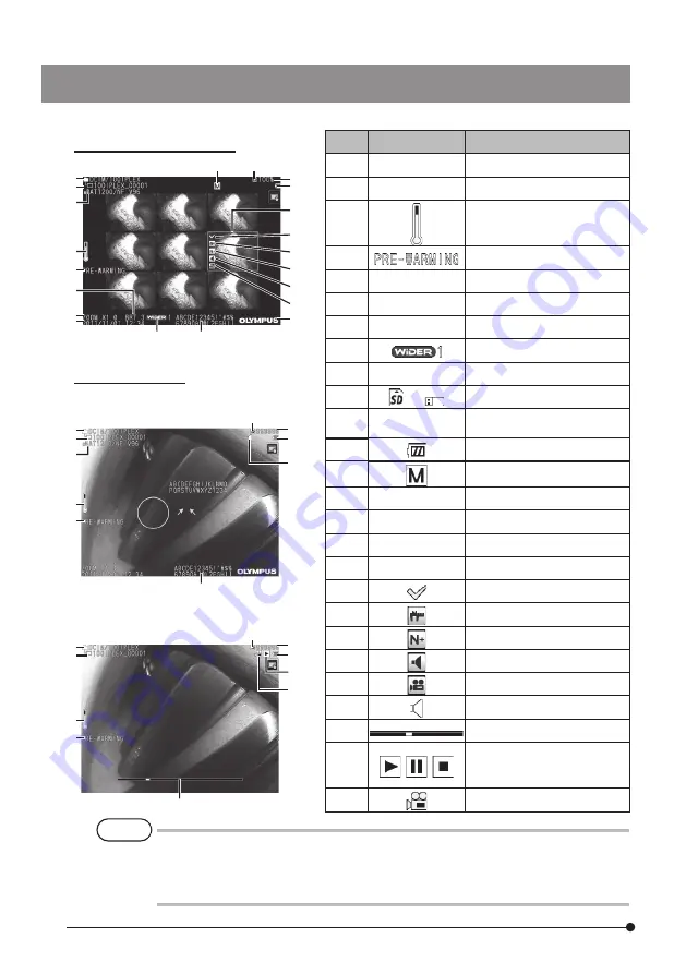
View screen
Thumbnail screen
No.
Icon/Indicator
Name
1
-
Folder name
2
-
Optical adapter name
3
Distal end temperature
indicator
4
Warming-up icon
5
-
Brightness level
6
-
Zoom level
7
-
Date/Time
8
WiDER icon
9
-
Title
10
or
Media icon (SD or USB)
11
-
Number of recordable
images
12
Battery indicator
19
Manual icon
20
-
Logo
21
-
File name
22
-
Remaining media capacity
23
-
Thumbnail selection frame
24
Mark
25
Measurement icon
26
Note icon
27
Sound icon
28
Movie icon
29
Playing back sound icon
30
Movie playback position bar
31
,
,
Movie playback status icon
(Playing back, pause or end
of playback)
32
Playing back movie icon
1
21
2
3
5
7
6
1
1
21
21
3
3
10
19
10
10
22
12
23
25
24
26
27
28
20
11
11
12
12
31
32
29
9
9
30
8
{ When playing back the still image
{ When playing back the movie
2
4
4
4
Содержание IPLEX NX IV9000N
Страница 8: ......
Страница 19: ...11 IPLEX NX Scope unit optional Model name serial number Label without description Caution Conformity label ...
Страница 121: ...113 IPLEX NX MEMO ...
Страница 124: ...MEMO ...


